
Electric pressure cooker with rapid pressure relief function

An electric pressure cooker, functional technology, applied in the field of pressure cooker, can solve the problems of wasting water resources, difficult cleaning by users, poor safety, etc., and achieve the effect of large market value, saving water resources, cooling and pressure relief quickly

Inactive Publication Date: 2012-04-04
GUANGDONG LUBY ELECTRONICS
View PDF6 Cites 66 Cited by
  • Summary
  • Abstract
  • Description
  • Claims
  • Application Information

AI Technical Summary

Problems solved by technology

There are the following problems in the method of opening the pressure relief valve to exhaust and reduce pressure: if there is liquid food in the pot, the food will be discharged from the exhaust port with the high-pressure airflow, which may burn the user, and the liquid food will fall on the pot cover, which is easy to breed Bacteria, causing hygiene problems, and difficult for users to clean
The natural cooling method has the following problems: the waiting time is relatively long, generally more than 30 minutes, if it is a plateau area, the waiting time is longer, which brings inconvenience to users
The existing technology has the problems of inconvenient operation, waste of water resources and poor safety

Method used


Image

  • Electric pressure cooker with rapid pressure relief function
  • Electric pressure cooker with rapid pressure relief function
  • Electric pressure cooker with rapid pressure relief function

Examples


Embodiment Construction

[0024] Such as Figure 1 to 7 As shown, the present invention will be described in detail below in conjunction with the accompanying drawings.

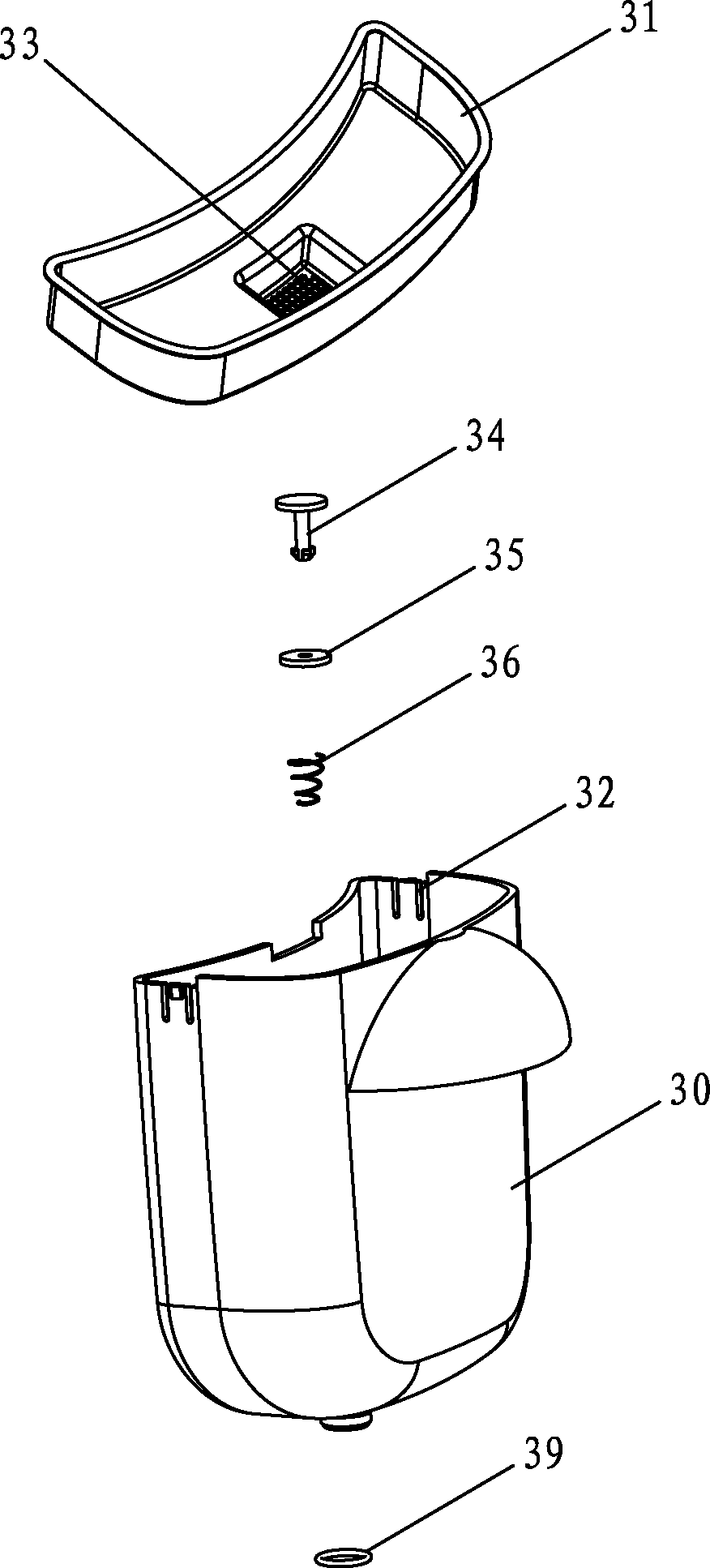
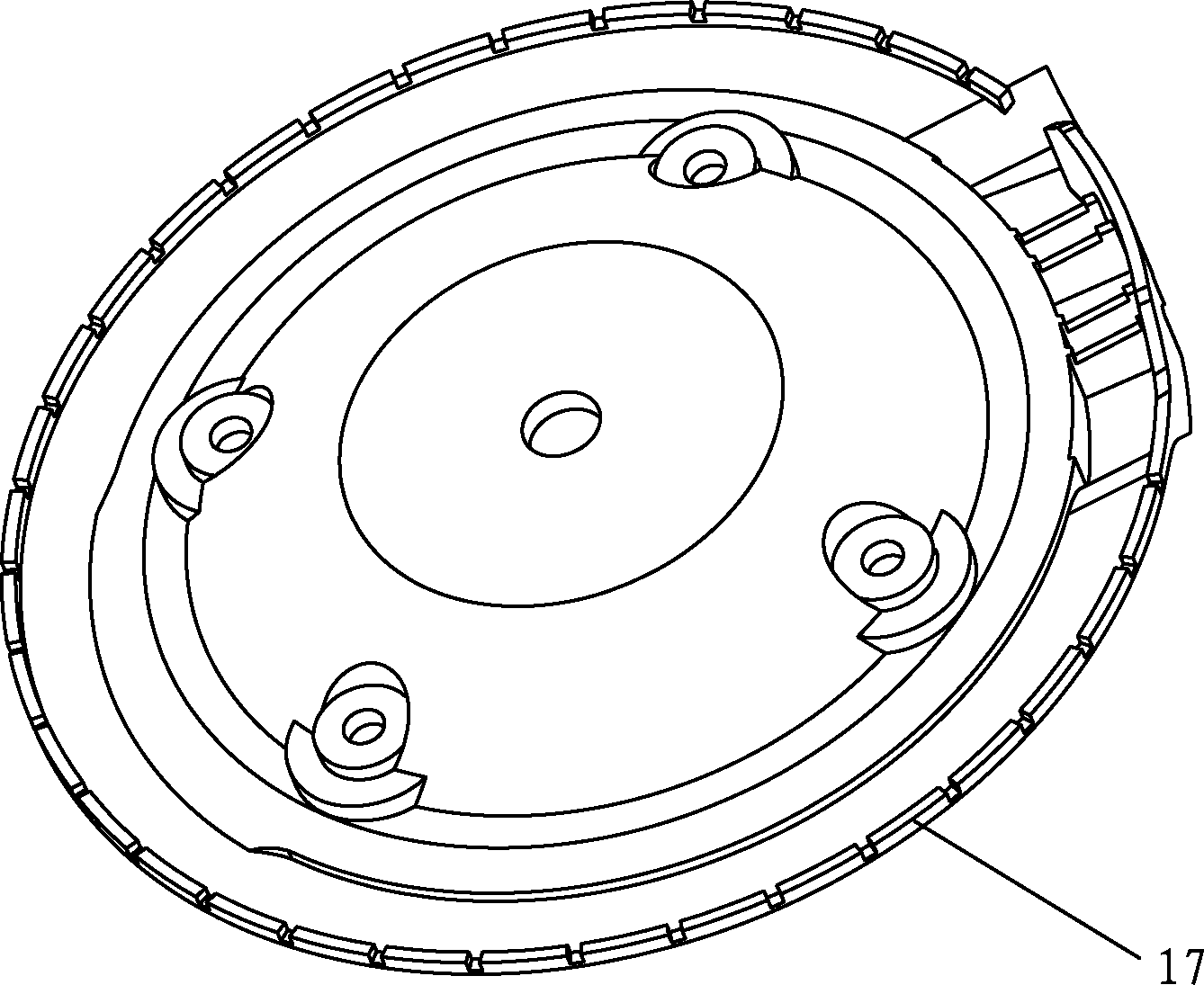
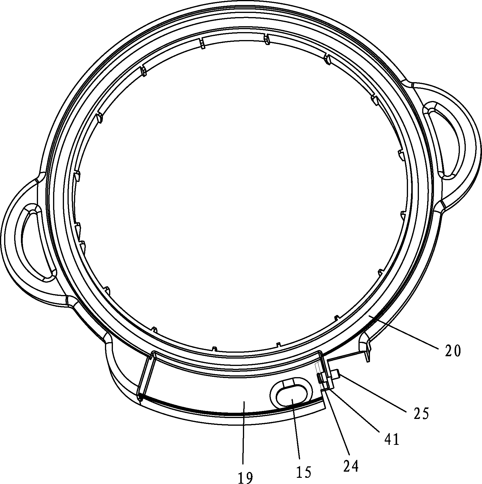
[0025] An electric pressure cooker with a quick pressure relief function, comprising a pot cover and a pot body. The pot cover includes a plastic surface cover 10 and a stainless steel cover 11. The pot body includes an upper liner seat 12 and a plastic shell 13, and the electric pressure cooker also includes a water pump 14 and The water tank, the water pump 14 is arranged inside the pot body, the water tank is arranged on the side of the pot body, the pot cover is provided with a water spray structure for flowing water to the upper surface of the stainless steel cover 11, and the upper gasket seat 12 is provided with A water collection structure for water flowing down from the surface. The bottom surface of the water collection structure is provided with a drainage hole 15, and the upper end of the water tank is provided with an openin...


PUM


Abstract

The invention relates to an electric pressure cooker with a rapid pressure relief function. The electric pressure cooker comprises a cooker cover and a cooker body, wherein the cooker cover comprises a plastic surface cover and a stainless steel cover; the cooker body comprises an upper gasket seat and a plastic shell; the electric pressure cooker also comprises a water pump and a water tank, wherein the water pump is arranged inside the cooker body, and the water tank is arranged on the lateral surface of the cooker body; the cooker cover is provided with a water spraying structure which is used for shunting water to the upper surface of the stainless steel cover; the upper gasket seat is provided with a water collecting structure which is used for receiving water flowing from the upper surface of the stainless steel cover; the bottom surface of the water collecting structure is provided with a water drainage hole; the upper end of the water tank is provided with an opening; the opening of the water tank is positioned below the water drainage hole; the water inlet of the water pump and the water outlet of the water tank are communicated; and the water outlet of the water pump and the water spraying structure are communicated. According to the electric pressure cooker disclosed by the invention, the water pump, the water tank, the water spraying structure and the water collecting structure are matched to realize circular temperature reduction of water; and the electric pressure cooker has the advantages of convenience for operation, water resource saving, good safety and high speed of temperature reduction and pressure relief.

Description

Technical field [0001] The invention relates to the technical field of pressure cookers, in particular to an electric pressure cooker with a quick pressure relief function. Background technique [0002] Electric pressure cookers are widely loved by people because they can cook quickly and have less nutritional loss in the food they cook. It has become one of the fast-growing appliances in the home appliance industry because of its time-saving, power-saving, and convenience. However, users who use electric pressure cookers cannot quickly open the lid after cooking food quickly and cannot enjoy the food immediately, which has become the biggest trouble for users who use electric pressure cookers. [0003] After the cooking work of the electric pressure cooker is finished, because of the high pressure in the pot, the pot body must be cooled down before the lid can be opened. Commonly used cooling methods include opening the pressure relief valve to exhaust and reduce the pressure co...

Claims


Application Information

Patent Timeline
IPC IPC(8): A47J27/08A47J27/09
CPCA47J27/092A47J27/0802A47J27/00A47J36/00
Inventor 龚盛鹏李中林
Owner GUANGDONG LUBY ELECTRONICS
Learn More