Spliced stamping mould

A stamping die and splicing technology, applied in the field of stamping die, can solve the problems of damage to the die surface, hidden dangers, low production efficiency, etc., to avoid material jams and ensure production efficiency.

Inactive Publication Date: 2012-04-04
CHONGQING HUAQING AUTOMOBILE PARTS
View PDF10 Cites 9 Cited by
  • Summary
  • Abstract
  • Description
  • Claims
  • Application Information

AI Technical Summary

Problems solved by technology

[0002] When the stamping process is carried out on the press, the workpiece is often stuck on the lower die and is not easy to take out, which affects the continuity of production and the production efficiency is low. Material rod, elastic ejector device, etc., in order to take out the workpiece from the lower mold, but the impact type punching rod will exert an impact force on the workpiece, which will not only cause damage to the workpiece, but also cause the workpiece to be disordered under the action of the impact force. The pop-up and scattered, the scene is chaotic, there are certain safety hazards, which is not conducive to automatic production; when using the elastic lifting device, it is usually set as a spring or elastic rubber to provide elastic force, the elastic force is related to the deformation, and the elastic force is a variable force , the performance will decrease after long-term use, and the elastic elements need to be replaced regularly, which is costly and is only used to provide elastic ejection force, which cannot guarantee that the workpiece will be ejected as required under the action of the ejection force. For workpieces with complex surface structures, the ejector The material function cannot be guaranteed, and the problem of material jams cannot be avoided. Once a material jam occurs, the continuous elastic force will obliquely jam the workpiece into the mold, making it more difficult to take out the workpiece, and even damage the mold surface.

Method used


Image

  • Spliced stamping mould
  • Spliced stamping mould
  • Spliced stamping mould

Examples


Embodiment Construction

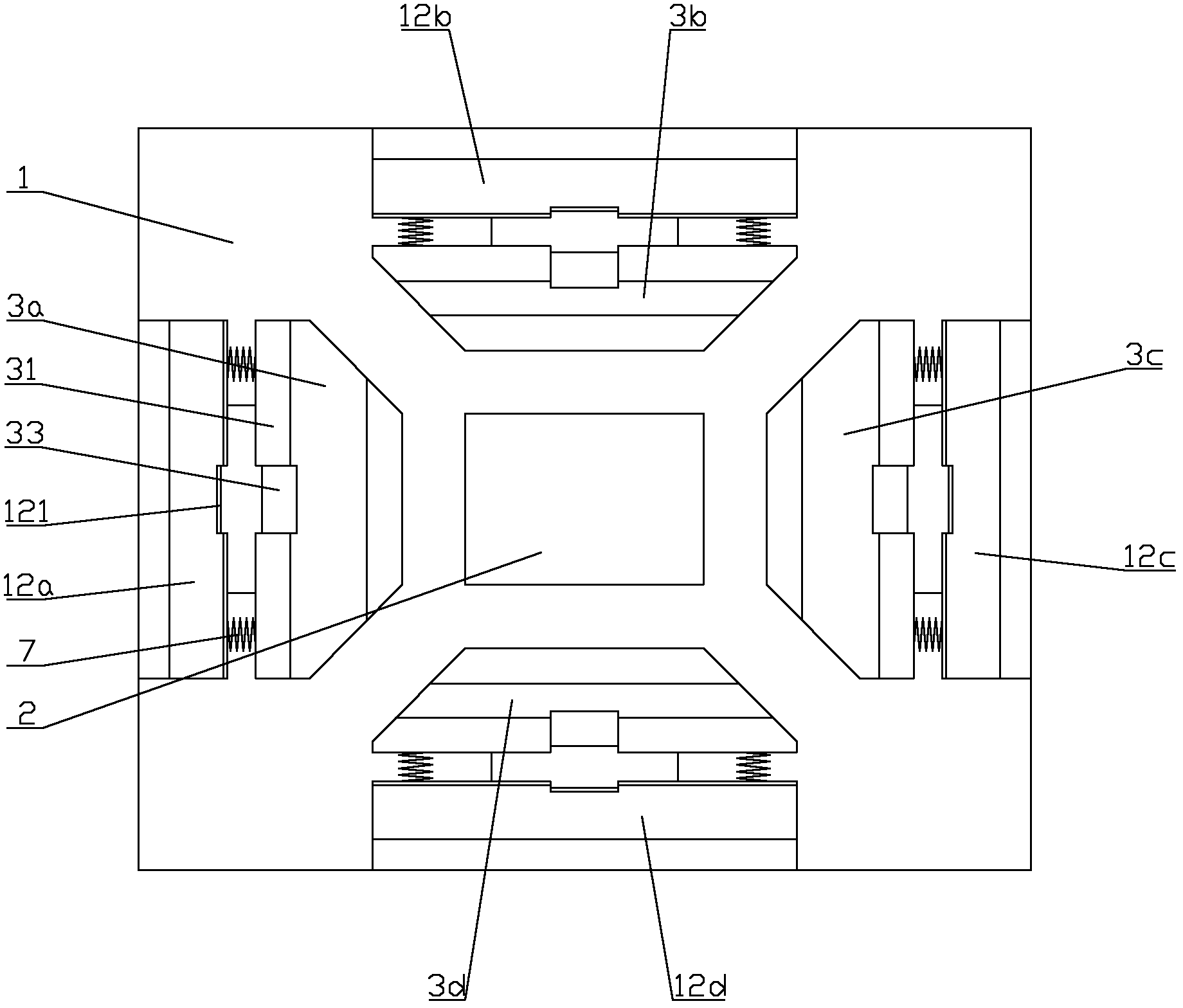
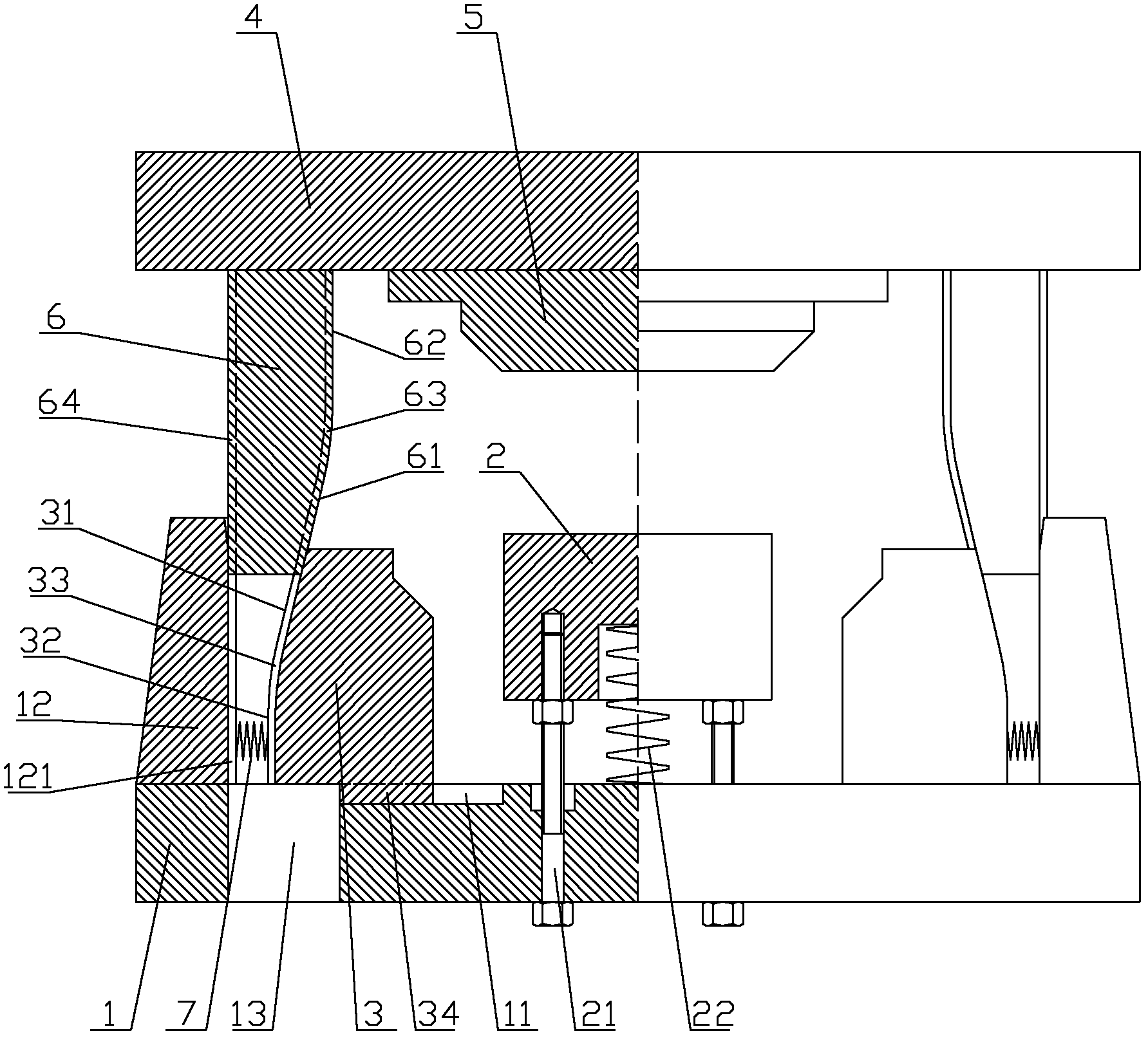
[0017] figure 1 It is a half sectional view of the present invention, figure 2 It is a plan view of the lower die of the present invention, as shown in the figure: the split stamping die of the present invention includes an upper die assembly and a lower die assembly, and the lower die assembly includes a lower die base 1, a supporting block 2 and a surrounding At least two lower die splicing blocks 3 that can be combined on the outside of the supporting block 2 and are slidably connected to the lower die base 1; the supporting block 2 is a liftable structure, and its top surface is a part of the lower die surface. The inner surface surrounded by the die splicing block 3 and the top surface of the supporting block 2 can be spliced ​​to form a complete lower die surface; the upper die assembly includes an upper die base 4, an upper die 5 and a push block 6, and the upper die 5 is fixedly arranged on the bottom surface of the upper mold base 4, and the bottom surface of the up...


PUM


Abstract

The invention discloses a spliced stamping mould. The mould comprises an upper mould component and a lower mould component, wherein the lower mould component comprises a lower mould seat, a material supporting block and at least two splicable lower mould splicing blocks which encircle the outer side of the material supporting block and are connected to the lower mould seat in a sliding mode; the material supporting block has a liftable structure; inner side surfaces encircled by splicing the lower mould splicing blocks and the top surface of the material supporting block can be spliced to form a complete lower mould surface; the upper mould component comprises an upper mould seat, an upper mould and push blocks; the upper mould is fixedly arranged on the bottom surface of the upper mould seat; and the push blocks encircle the outer side of the upper mould, correspond to the lower mould splicing blocks one to one and are used for pushing the corresponding lower mould splicing blocks for splicing when a workbench on a stamping machine descends. The lower mould of the spliced stamping mould has a spliced structure, each lower mould splicing block can move to the outer side to be separated from a workpiece along the horizontal direction after stamping forming, the workpiece is supported by the material supporting block, the top surface of the material supporting block is a part of lower mould surface, and the contact area of the material supporting block and the workpiece is relatively small, so that the workpiece with a complex surface structure is easy to take out, material blocking can be effectively avoided, and production efficiency can be ensured.

Description

technical field [0001] The invention relates to a stamping die, in particular to a split stamping die. Background technique [0002] When the stamping process is carried out on the press, the workpiece is often stuck on the lower die and is not easy to take out, which affects the continuity of production and the production efficiency is low. Material rod, elastic ejector device, etc., in order to take out the workpiece from the lower mold, but the impact type punching rod will exert an impact force on the workpiece, which will not only cause damage to the workpiece, but also cause the workpiece to be disordered under the action of the impact force. The pop-up and scattered, the scene is chaotic, there are certain safety hazards, which is not conducive to automatic production; when using the elastic lifting device, it is usually set as a spring or elastic rubber to provide elastic force, the elastic force is related to the deformation, and the elastic force is a variable forc...

Claims


Application Information

Patent Timeline
Patent Type & Authority Applications(China)
IPC IPC(8): B21D37/10B21D45/04
Inventor 唐舜清唐云峰郑凯
Owner CHONGQING HUAQING AUTOMOBILE PARTS
Why Eureka
Try Eureka