Rotated riveting device

A riveting head and tooling technology, applied in the field of riveting equipment, can solve the problems of low production efficiency, complex structure, low riveting precision, etc., achieve good riveting effect, simple device structure, and improve work efficiency

Inactive Publication Date: 2012-04-04
SUZHOU RISING AUTO PARTS
View PDF4 Cites 4 Cited by
  • Summary
  • Abstract
  • Description
  • Claims
  • Application Information

AI Technical Summary

Problems solved by technology

The structure of the existing riveting equipment is relatively complicated, and the riveting accuracy is not high, and the production efficiency is low

Method used


Image

  • Rotated riveting device
  • Rotated riveting device

Examples


Embodiment Construction

[0019] The present invention will be further described below in conjunction with the accompanying drawings and embodiments.

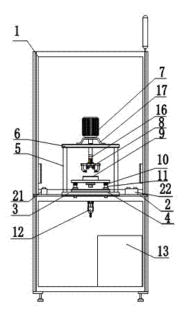
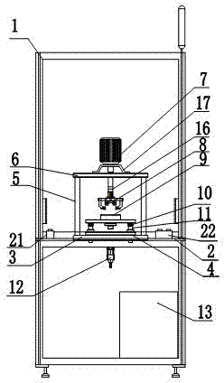
[0020] Such as figure 1 As shown in Fig. 2, the spin riveting device of the present invention includes a frame 1, a table top 2 is provided in the middle of the frame 1, a lower supporting surface 3 is provided on the table top 2, and on the lower supporting surface 3 A fixed plate 4 and a support column 5 are provided, an upper support surface 6 is provided on the support column 5, a motor 7 is provided on the upper support surface 6, the output end of the motor 7 is connected to a spin riveting head 8, and the lower tooling 9 passes through Spring 10 and guide column 11 are connected with cylinder 12, and electric box 13 is located at the bottom of described frame 1; In the opposite direction of described table top 2 operation, be provided with three-point assembly 14; Described motor 7 passes thrust bearing 15, spline The shaft 16 is connected with ...


PUM


Abstract

The invention relates to a rotated riveting device, comprising a machine frame, a table board arranged in the middle of the machine frame, a lower supporting face arranged on the table board, the lower supporting face being provided with a dead plate and a supporting column, the supporting column being provided with an upper supporting face, a motor being arranged on the upper supporting face. The output end of the motor is connected with the head of rotated riveter. The lower equipment is connected with a cylinder via a spring and a guide column. The electricity box is arranged below the machine frame. The invention is simple in structure and by adopting rotated riveter head structure, has sound effect in riveting edges and improves working efficiency.

Description

technical field [0001] The invention belongs to mechanical assembly equipment, in particular to a spin riveting equipment. Background technique [0002] Rotary riveting equipment (rotary riveting machine), also known as riveting machine, riveting press, riveting machine and riveting machine, is widely used in electronic appliances, instruments and meters, watch components, automobile and motorcycle accessories, textile equipment, machinery, construction, photographic equipment All kinds of riveting in the production of , hardware tools, medical equipment, daily necessities, cultural and sports products and other industries. [0003] The structure of the rotary riveting equipment is mainly composed of a motor, a main shaft, a riveting head and a riveting head pressing mechanism. The structure of the existing riveting equipment is relatively complicated, and the riveting precision is not high, and the production efficiency is low. Contents of the invention [0004] Purpose...

Claims


Application Information

Patent Timeline
Patent Type & Authority Applications(China)
IPC IPC(8): B21J15/12
Inventor 岳胜桥龚达锦朱海峰朱俊严刚秦星勇钱镛棱汤自知
Owner SUZHOU RISING AUTO PARTS
Why Eureka
Try Eureka