Bucket type conveyor
A conveyor and bucket type technology, applied in the field of bucket conveyors, achieves the effect of simple overall structure, convenient installation, use and maintenance, and improved conveying efficiency
- Summary
- Abstract
- Description
- Claims
- Application Information
AI Technical Summary
Problems solved by technology
Method used
Image

Examples
Embodiment Construction
[0020] In order to enable the examiners of the patent office, especially the public, to understand the technical essence and beneficial effects of the present invention more clearly, the applicant will describe in detail the following in the form of examples, but none of the descriptions to the examples is an explanation of the solutions of the present invention. Any equivalent transformation made according to the concept of the present invention which is merely formal but not substantive shall be regarded as the scope of the technical solution of the present invention.
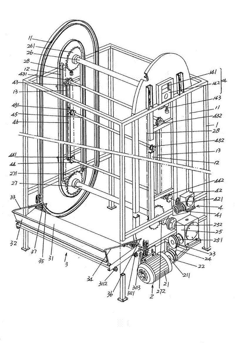
[0021] Please see figure 1 , a frame-type and preferably hollow-shaped frame 1 is provided, which is formed as a cuboid in this embodiment. at present figure 1 The position state shown is taken as an example (hereinafter the same). On both sides (left and right sides) of the frame 1 and at positions facing each other, a first ring-shaped guide rail 11 with the same shape and size is fixed respectively...
PUM
 Abstract
Description
Claims
Application Information
 - Generate Ideas
- Intellectual Property
- Life Sciences
- Materials
- Tech Scout
- Unparalleled Data Quality
- Higher Quality Content
- 60% Fewer Hallucinations
Browse by: Latest US Patents, China's latest patents, Technical Efficacy Thesaurus, Application Domain, Technology Topic, Popular Technical Reports.
© 2025 PatSnap. All rights reserved.Legal|Privacy policy|Modern Slavery Act Transparency Statement|Sitemap|About US| Contact US: help@patsnap.com