Crane luffing control valve and crane luffing hydraulic system

A technology for controlling valves and cranes, applied in cranes, mechanical equipment, fluid pressure actuating devices, etc., can solve the problems of changing control methods and high production costs, and achieve elimination of jitter, improvement of control accuracy, and improvement of stability and fretting. Effect

Active Publication Date: 2012-04-04
XUZHOU HEAVY MASCH CO LTD
View PDF6 Cites 9 Cited by
  • Summary
  • Abstract
  • Description
  • Claims
  • Application Information

AI Technical Summary

Problems solved by technology

However, this system needs to match complex balance valves and change the control mode, and the production cost is relatively high

Method used


Image

  • Crane luffing control valve and crane luffing hydraulic system
  • Crane luffing control valve and crane luffing hydraulic system
  • Crane luffing control valve and crane luffing hydraulic system

Examples


Embodiment Construction

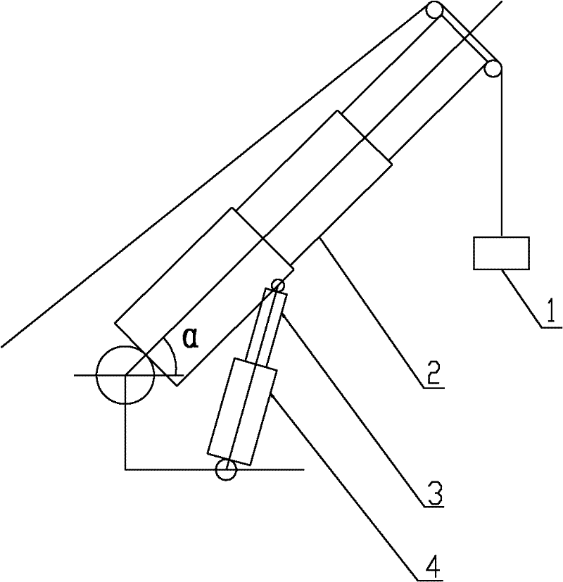
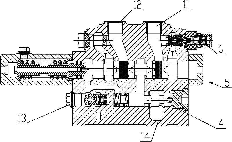
[0046] The core of the invention is to provide a crane luffing control valve. The control valve can significantly improve the micro-movement of the crane when it is luffing, and eliminate the shaking phenomenon when the handle is slightly opened.

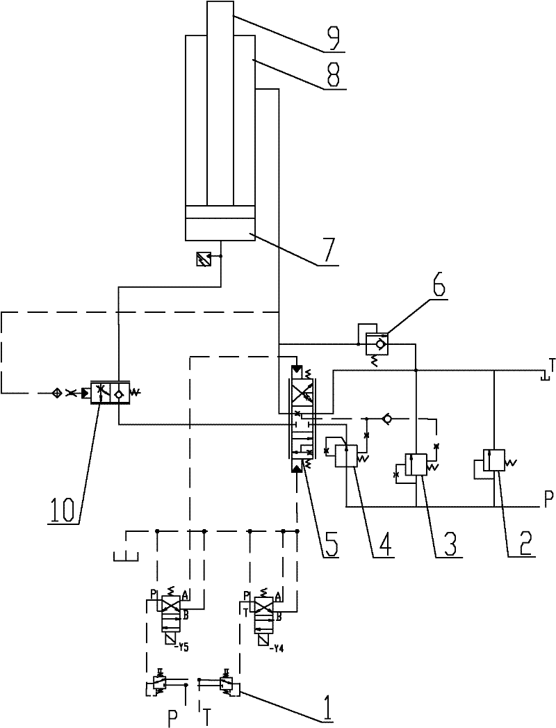
[0047] Another core of the present invention is to provide a crane luffing hydraulic system provided with the crane luffing control valve.

[0048] In order to enable those skilled in the art to better understand the solution of the present invention, the present invention will be further described in detail below in conjunction with the accompanying drawings and specific embodiments.

[0049] In this article, terms such as "up, down, left, right" indicating orientation are based on the positional relationship of the drawings, and should not be interpreted as an absolute limitation on the scope of protection. Similarly, terms such as "first, second" It is only for the convenience of description to distinguish different components w...


PUM


Abstract

The invention discloses a crane luffing control valve, comprising a valve body and a valve core. The valve body is provided with an oil inlet, a first oil outlet, a second oil outlet and an oil return opening. One end of the valve core seals the second oil outlet shoulder and is equipped with a first groove for connecting the oil inlet and the second oil outlet; the other end of the valve core is equipped with a second groove for connecting the second oil outlet and the oil return opening; at least one of the second groove and the first groove has an axial spacing less than a width of an under cut groove of the second oil outlet. The control valve can substantially enhance jiggle characteristic of the crane during luffing and eliminate jitter phenomenon of a handle in a micro opening. The invention also discloses a crane luffing hydraulic system equipped with the crane luffing control valve.

Description

technical field [0001] The invention relates to the technical field of engineering machinery, in particular to a hydraulic control valve for controlling the amplitude-changing action of the main arm of a crane. The invention also relates to a crane luffing hydraulic system provided with the control valve. Background technique [0002] Before the lifting operation of the truck crane, the main arm needs to be luffed to a certain angle. During the lifting operation, the main arm needs to be frequently raised and lowered by the luffing, especially when the heavy object is precisely positioned by the luffing. The stability and fretting of the amplitude are particularly important. [0003] Please refer to figure 1 , figure 1 It is the schematic diagram of the luffing mechanism of the existing truck crane. [0004] As shown in the figure, when the hydraulic system controls the extension of the piston rod 3' of the luffing cylinder 4', the crane main arm 2' rotates counterclockw...

Claims


Application Information

Patent Timeline
Patent Type & Authority Applications(China)
IPC IPC(8): B66C23/82F15B13/04
Inventor 东权刘东宏胡金萍崔向坡
Owner XUZHOU HEAVY MASCH CO LTD
Why Eureka
Try Eureka