Sealed compressor

A technology of closed compressors and opening and closing parts, which is applied in the direction of liquid variable capacity machinery, mechanical equipment, variable capacity pump components, etc., and can solve the problem of increasing working time, increasing the discharge valve from the accurate position, and assembling the discharge valve assembly Improve the assembly performance and reduce the failure rate

Active Publication Date: 2012-04-04
SAMSUNG ELECTRONICS CO LTD
View PDF15 Cites 4 Cited by
  • Summary
  • Abstract
  • Description
  • Claims
  • Application Information

AI Technical Summary

Problems solved by technology

[0012] However, as described above, for the structure in which the discharge valve is fixed to the valve plate by combining rivets only on one side end, during the assembly process of the discharge valve assembly, there will be increased H

Method used


Image

  • Sealed compressor
  • Sealed compressor
  • Sealed compressor

Examples


Embodiment Construction

[0031] Hereinafter, the structure of a hermetic compressor according to a preferred embodiment of the present invention will be described in detail with reference to the accompanying drawings.

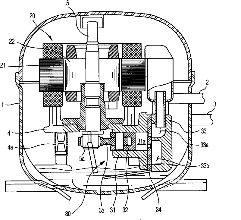
[0032] like figure 1 As shown, the hermetic compressor according to the present invention has an appearance formed by a hermetic container 1 . One side of the airtight container 1 is connected with a suction guide pipe 2 that guides the refrigerant in the pre-compression state to the inside of the airtight container 1, and the other side of the airtight container 1 is connected with the refrigerant that will be compressed in the airtight container 1 and discharged. The discharge guide pipe 3 leading to the outside of the airtight container 1 .

[0033] In addition, a compression unit 30 for compressing the refrigerant and a driving unit 20 for providing a driving force for compressing the refrigerant are arranged inside the airtight container 1, and the compression unit 30 and the dri...


PUM


Abstract

The invention discloses a sealed compressor. The sealed compressor comprises a discharge valve installing member having a discharge valve equipped on one side surface of a valve plate and applied for opening and closing discharge holes of the valve plate; and a jointing part applied for fixing the discharge valve installing member on the valve plate and having a first jointing part and a second jointing part. The two ends of the discharge valve are fixed on the valve plate respectively through the first jointing part and the second jointing part. Therefore, the discharge valve installing member is convenient to install. Meanwhile, the reject ratio of the discharge valve installing member can be effectively reduced during an installing process.

Description

technical field [0001] The invention relates to a hermetic compressor, in particular to a hermetic compressor capable of improving the assembly of a discharge valve assembly and effectively reducing the failure rate occurring in the assembly process of the discharge valve assembly. Background technique [0002] Generally, a hermetic compressor refers to a device used in a refrigeration cycle system of a refrigerator or an air conditioner to compress refrigerant. [0003] This hermetic compressor forms the exterior with an airtight container. One side of the airtight container is connected with a suction guide pipe that guides the refrigerant in an uncompressed state to the inside of the airtight container, while the other side of the airtight container is connected with a suction guide pipe that guides the refrigerant compressed in the airtight container to the airtight airtight container. Discharge guide tube outside the container. [0004] And, a compression unit perform...

Claims


Application Information

Patent Timeline
IPC IPC(8): F04B39/10
Inventor 郑龙衍崔容豪
Owner SAMSUNG ELECTRONICS CO LTD
Why Eureka
Try Eureka