Vacuum collector tube

A vacuum collector tube, vacuum degree technology, applied in heating devices, solar thermal devices, solar thermal power generation and other directions, can solve the problems of low heat exchange efficiency, inability to quickly increase the thermosiphon head, etc., to reduce consumption and improve heat exchange. Efficiency, material reduction effect

Inactive Publication Date: 2012-04-04
浙江创新电器科技有限公司
View PDF5 Cites 1 Cited by
  • Summary
  • Abstract
  • Description
  • Claims
  • Application Information

AI Technical Summary

Problems solved by technology

[0003] The present invention aims to solve the shortcomings of the existing vacuum heat collecting tubes that the thermosiphon pressure head cannot be quickly raised and the heat exchange efficiency is not high, and provides a vacuum heat collection tube that can quickly lift the thermosiphon pressure head and have low heat exchange efficiency

Method used


Image

  • Vacuum collector tube
  • Vacuum collector tube
  • Vacuum collector tube

Examples


Embodiment Construction

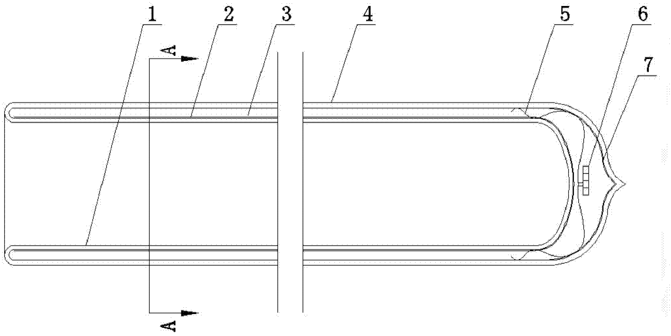
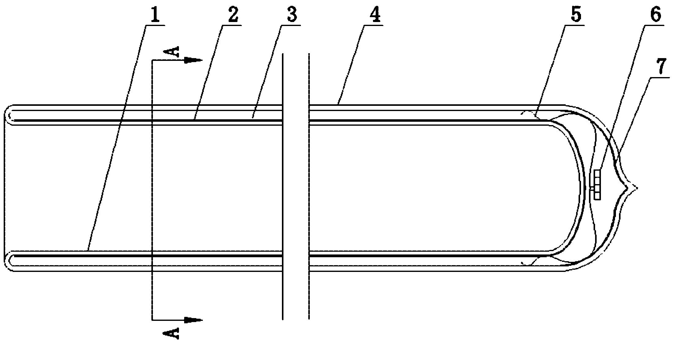
[0012] Referring to the attached picture:

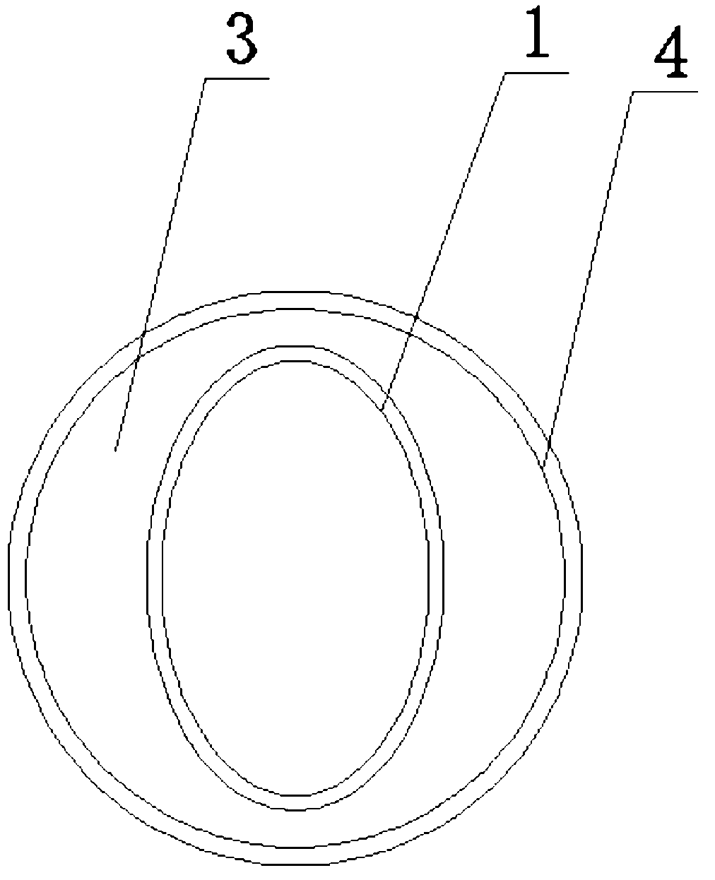
[0013] The vacuum heat collecting tube of the present invention comprises an oval inner glass tube 1 and a circular cover glass tube 4, the oval inner glass tube 1 is sealed with a round bottom, and the surface of the oval inner glass tube 1 is coated with a sun selective Absorbent coating 2, the opening end of the oval inner glass tube 1 is sealed with the opening end of the cover glass tube 4, the round bottom of the oval inner glass tube 1 is provided with a spring support frame 5 and the inner wall tension of the cover glass tube 4 Tightly fixed, there is a vacuum interlayer 3 between the oval inner glass tube 1 and the cover glass tube 4, and there is a getter 6 to maintain the vacuum degree of the vacuum interlayer 3.

[0014] The short axis of the cross-section of the oval inner glass tube 1 faces the sunlight. Generally, the direction of the short axis is set according to the direction of the strongest sunlight at noon. Whe...


PUM


Abstract

The invention discloses a vacuum collector tube, which comprises an elliptical inner glass tube and a circular cover glass tube. The circular bottom of the elliptical inner glass tube is enclosed; the surface of the elliptical inner glass tube is plated with a solar selective absorption coating; the opening end of the elliptical inner glass tube is connected with the opening end of the circular cover glass tube in a sealing way; the circular bottom of the elliptical inner glass tube is provided with a spring support frame which is fixed with the inner wall of the cover glass tube in a tensioning way; a vacuum sandwich is formed between the elliptical inner glass tube and the circular cover glass tube, and the vacuum degree of the sandwich is maintained by a getter. The vacuum collector tube has the advantages of quick temperature rise, high heat exchange efficiency, low consumption of glass materials.

Description

technical field [0001] The invention relates to a vacuum heat collecting tube for a solar true water heater. Background technique [0002] Ordinary solar vacuum heat collector tubes are made of concentric circles inside and outside, sealed by inner and outer glass tubes, and vacuumized in the interlayer. Because the circular surface structure has the largest volume, the vacuum tube has a large water capacity, which makes the vacuum tube unable to The rapid increase of the thermosiphon pressure head causes the disadvantage of low heat exchange efficiency. Contents of the invention [0003] The present invention solves the shortcomings of the existing vacuum heat collecting tubes that the thermosiphon pressure head cannot be quickly raised and the heat exchange efficiency is not high, and provides a vacuum heat collection tube with a rapid rise of the thermosiphon pressure head and low heat exchange efficiency. [0004] The vacuum heat collecting tube is characterized in th...

Claims


Application Information

Patent Timeline
Patent Type & Authority Applications(China)
IPC IPC(8): F24J2/46
CPCY02E10/40
Inventor 夏志生
Owner 浙江创新电器科技有限公司
Why Eureka
Try Eureka