Three-dimensional shape measuring device
A three-dimensional shape, measuring device technology, used in measuring devices, using optical devices, charging systems, etc.
- Summary
- Abstract
- Description
- Claims
- Application Information
AI Technical Summary
Problems solved by technology
Method used
Image

Examples
no. 1 approach
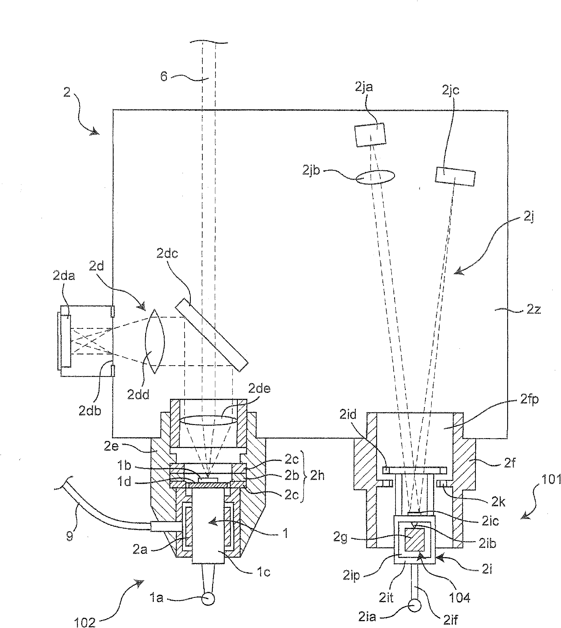
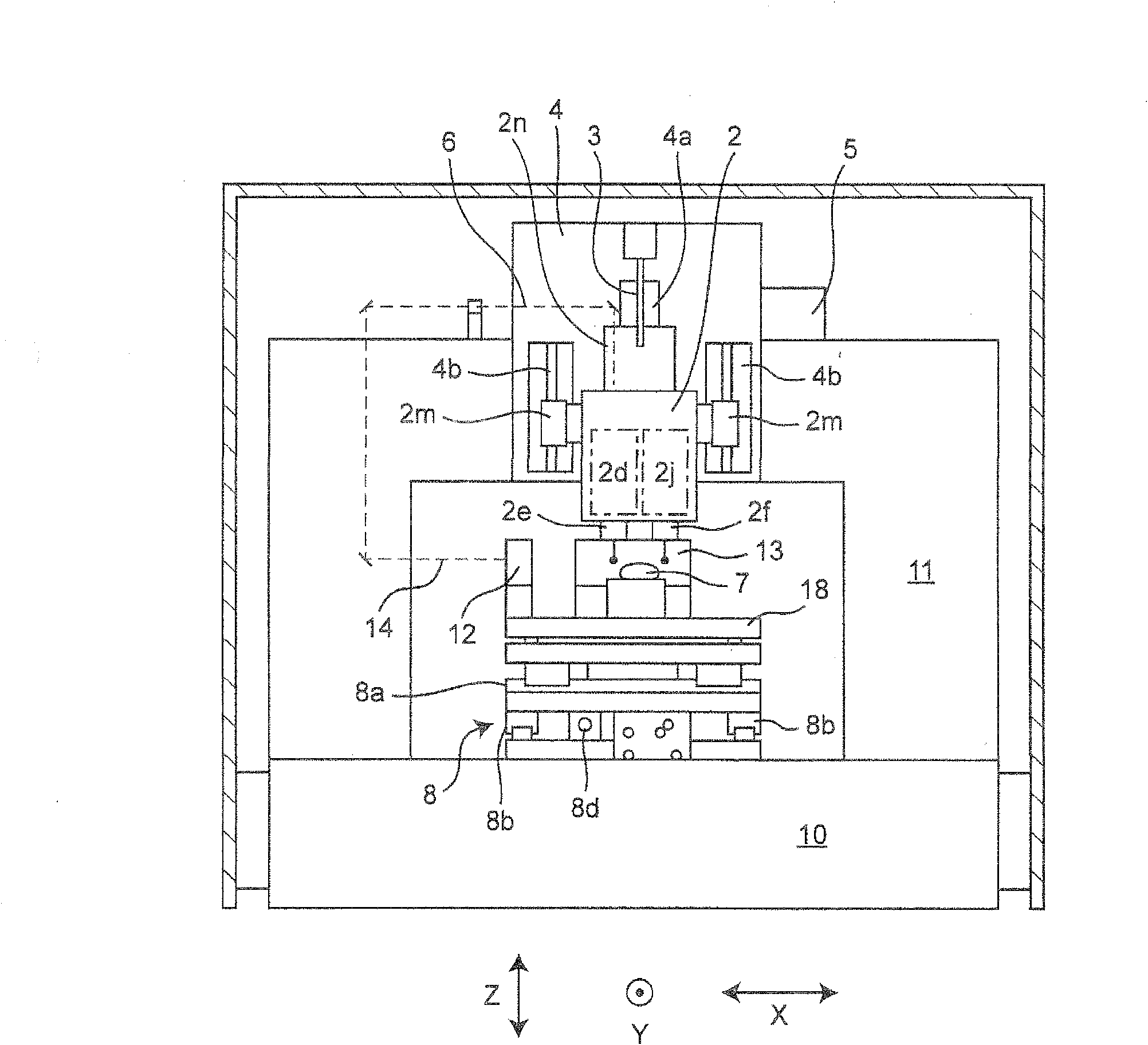
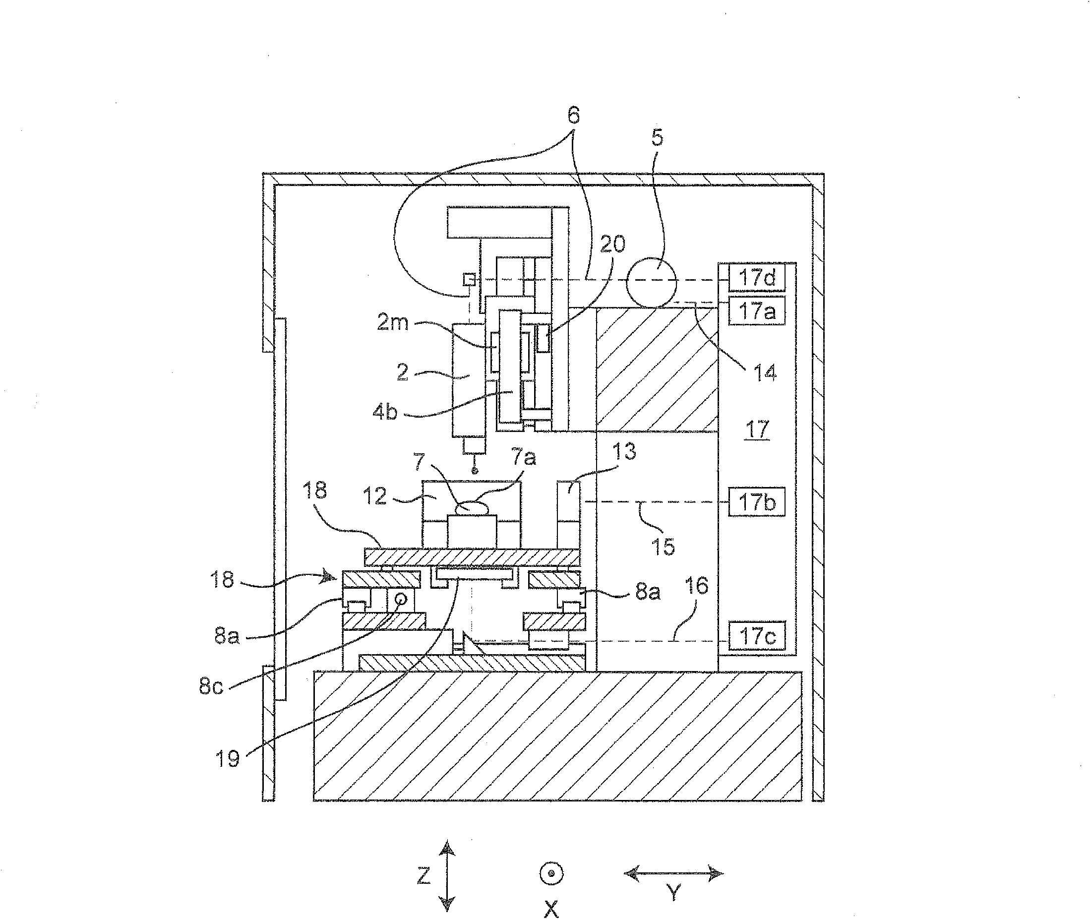
[0103] figure 1 It is an enlarged front view of the first movable part 1 and the second movable part 2 including the movable inclined part 2i of the three-dimensional shape measuring device according to the first embodiment of the present invention. figure 2 is a front view of the shape measuring device according to the first embodiment of the present invention, image 3 It is a right side view of the shape measuring device according to the first embodiment of the present invention. Figure 4 It is an explanatory diagram showing an example of the control structure when measuring the upper surface 7a of the measurement object 7 with the upper surface contactor 1a of the shape measuring apparatus according to the first embodiment of the present invention. Figure 5 It is an explanatory diagram showing an example of the control configuration when measuring the side surface 7b of the measurement object 7 with the side contact 2ia of the shape measuring device according to the fi...
no. 2 approach
[0186] Figure 8A and Figure 8B A laser light path used for XYZ coordinate measurement of the second embodiment of the present invention is shown.
[0187] and Figure 7A and Figure 7B It can be seen that Figure 8A and Figure 8B Here, instead of the Y reference mirror 13, a long Y reference mirror 22 longer than the Y reference mirror 13 is installed, and a steady laser 23 for side Y coordinate measurement is added. This is because, Figure 7A and Figure 7B In the structure of , the XY drive unit 8 only needs to move without tilting at all, but if it tilts due to swaying, an error occurs in the Y coordinate measurement data, so the Y coordinate is measured on the axis of the side contact 2ia. Also, the long Y reference mirror 22 needs to be longer than the Y reference mirror 13 by an amount corresponding to the distance between the top contact 1a and the side contact 2ia. In addition, it has been explained to use a plurality of half-mirrors to separate the steady-...
no. 3 approach
[0192] As described in the first embodiment, when measuring with the side contact 2ia, the Z coordinate of the upper contact 1a is used as the Z2 position, and the upper contact 1a and the pneumatic slider 1c are weak in the Z-axis direction. Acceleration and the like during the action of the movable part 2 sometimes produce, for example, vibrations of about 200 nanometers ( Figure 9A ).
[0193] In this case, it is necessary to newly install an air slider vibration stop device 82 functioning as an example of the first movable part operation stop device as follows, and the air slider vibration stop device 82 prevents The movement of the air slider 1c in the Z-axis direction can prevent the vibration of the air slider 1c. For example, as a pneumatic slider vibration stop device 82 such as Figure 4 , Figure 5 and Figure 9AAs shown, a switching valve 43 is provided on the piping 83 that supplies compressed air to the air bearing 2a, and the switching valve 43 is connected...
PUM
| Property | Measurement | Unit |
|---|---|---|
| Diameter | aaaaa | aaaaa |
Abstract
Description
Claims
Application Information
 - R&D Engineer
- R&D Manager
- IP Professional
- Industry Leading Data Capabilities
- Powerful AI technology
- Patent DNA Extraction
Browse by: Latest US Patents, China's latest patents, Technical Efficacy Thesaurus, Application Domain, Technology Topic.
© 2024 PatSnap. All rights reserved.Legal|Privacy policy|Modern Slavery Act Transparency Statement|Sitemap