Connector

A technology for connectors and mating connectors, which is applied in the direction of connection, two-part connection devices, parts of connection devices, etc., to achieve the effects of improving assembly and pulling out operability, improving pulling out operability, and realizing miniaturization

Inactive Publication Date: 2012-04-04
HIROSE ELECTRIC GROUP
View PDF7 Cites 6 Cited by
  • Summary
  • Abstract
  • Description
  • Claims
  • Application Information

AI Technical Summary

Problems solved by technology

Therefore, it is difficult to insert the holder from the base end side of the housing, to bring the holder into contact with and press the respective connection terminals arranged in separate spaces inside the housing.

Method used


Image

  • Connector
  • Connector
  • Connector

Examples


no. 1 Embodiment approach

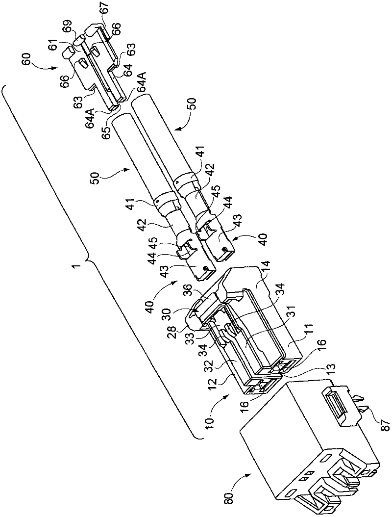
[0046] figure 1 A connector and a mating connector according to the first embodiment of the present invention are shown. Such as figure 1 As shown, the connector 1 according to the first embodiment of the present invention includes a housing 10, two connection terminals 40 mounted on the end of a cable 50 and accommodated in the housing 10, and holding each connection terminal 40 and each cable. Holder 60 for wire 50 . The front end side of the case 10 is separated, thereby securing a long creeping distance between the connection terminals 40 and improving the pressure resistance between the connection terminals 40 . Furthermore, the connector 1 has a locking mechanism 30 that engages with the mating connector 80 . When the connector 1 is inserted into the mating connector 80 , the locking mechanism 30 engages with the mating connector 80 , and the connector 1 and the mating connector 80 are locked to each other so that they are not easy to disengage.

[0047] Connector 1 ...

no. 2 Embodiment approach

[0071] Figure 10 It is a plan view showing the housing of the connector according to the second embodiment of the present invention. Such as Figure 10 As shown, based on the connector 100 of the second embodiment of the present invention, the front end side of the housing 110 is divided into three separate parts 111, 112, 113, and between the separate part 111 and the separate part 112, the separate part 112 and the separate part There are gaps 114 between the portions 113, respectively. Furthermore, a coupling portion 115 where the separation portions 111 , 112 , 113 are coupled is formed on the base end side of the housing 110 . In each separation part 111, 112, 113, like the above-mentioned connector 1 according to the first embodiment of the present invention, a terminal accommodating part opening to the front end side of the housing 110 is formed, and each terminal accommodating part accommodates and connects terminals. In addition, a cable insertion portion opening...


PUM


Abstract

Provided is a connector having a locking mechanism and a separate front end, realizing miniaturization, and improving assembling capability and extracting operability. In the connector (1), two arms form the arm of the locking mechanism (30). One end of the arm portion (31) is fixed to separating portion (11) while one end of the arm portion (32) is fixed to the separation portion (12). A connecting portion is utilized for connecting the other end of the arms. When the connector is installed to the insertion portion of the connector of the coupling connector (80), the separating wall arranged at the insertion portion of the connector of the coupling connector enters between the separating section (11) and the separating section (12) and enters between the arm portion (31) and the arm portion (32) as well. According to the structure, the arm portions (31, 32) can be extended. Moreover, a clamping operation section (36) can be arranged at the other end portion of the arm portions.

Description

technical field [0001] The present invention relates to connectors having a locking mechanism that engages with a mating connector. Background technique [0002] For example, in Patent Document 1 figure 1 As shown in FIG. 2 , connectors of this type are widely known as the front end side of the connector housing, which is inserted into the mating connector, is separated, and connection terminals are respectively provided inside these separated parts. By separating the front end side of the case, a long creeping distance between the connection terminals can be ensured, and the pressure resistance between the connection terminals can be improved. This type of connector is usually used as a connector for high voltage. [0003] On the other hand, as in the literature Figure 6 As shown, the connector described in Patent Document 1 is provided with a locking mechanism. When the connector is inserted into the mating connector, the locking mechanism engages with the mating conn...

Claims


Application Information

Patent Timeline
Patent Type & Authority Applications(China)
IPC IPC(8): H01R13/40H01R13/58H01R13/633H01R13/639H01R24/00
Inventor 坂下隆吉
Owner HIROSE ELECTRIC GROUP
Why Eureka
Try Eureka