High-voltage combined electrical apparatus

A combined electric appliance and high-voltage technology, which is applied in the high-pressure field, can solve the problems of high pressure, difficulty in breaking the induced current, and slow breaking speed of the grounding interface, so as to meet the requirements of reducing manufacturing difficulty, realize closing and closing short-circuit current, and ensure The effect of insulation performance

Active Publication Date: 2012-04-04
SHENYANG HUADE HIGH TECH ELECTRIC CO LTD
View PDF9 Cites 23 Cited by
  • Summary
  • Abstract
  • Description
  • Claims
  • Application Information

AI Technical Summary

Problems solved by technology

[0003] Insulation bushings in the prior art are usually insulated with sulfur hexafluoride gas, and some are insulated with high-pressure dry air, but they all have the risk of leakage and bursting;
[0004] In the prior art, the fast grounding switch is driven by the rotation of the transmission shaft of the external electric spring operating mechanism to drive the moving contact to reciprocate and linearly move, so as to realize the opening and closing of the grounding switch. Since the transmission of multiple components of the operating mechanism is required, The breaking speed between the grounding fractures is still slow, so if the grounding fractures are filled with dry air or nitrogen, it is very difficult to break the induced current, and the arc is not easy to extinguish, and SF6 gas with good insulation ability must also be used as insulation gas;
[0005] The movement speed of the moving contact of the three-position switch in the prior art is relatively slow. If

Method used


Image

  • High-voltage combined electrical apparatus
  • High-voltage combined electrical apparatus
  • High-voltage combined electrical apparatus

Examples


Embodiment Construction

[0066] Specific embodiments of the present invention are provided below in conjunction with the accompanying drawings.

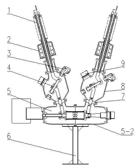
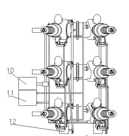
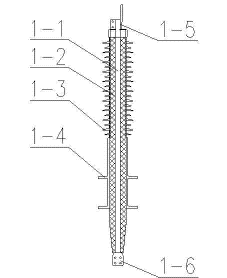
[0067] Such as figure 1 and figure 2 As shown, the technical solution adopted in the present invention includes a high-voltage vacuum circuit breaker 5, a three-position switch, a quick grounding switch 3 and a solid insulating bushing 1. The high-voltage vacuum circuit breaker 5 is a three-phase independent structure, and each phase is The recumbent tank structure is installed on the bracket 6 through the tank body 5-2. The left side of the high-voltage vacuum circuit breaker 5 is connected to the circuit breaker operating mechanism 10 through a linkage mechanism, and each phase of the high-voltage vacuum circuit breaker 5 is connected to a For the disc bushing 7, the high-voltage vacuum circuit breaker 5 and the isolating switch tank 8 are divided into two air chambers, the top of each disc-shaped bushing 7 is connected to the isolating switch tank 8, an...


PUM


Abstract

A high-voltage combined electrical apparatus is disclosed, which overcomes the following problems that: in the existing high-voltage combined electrical apparatus, an insulating sleeve has the dangers of leakage and explosion; the on/off induced current and the on/off bus transfer current of a three-position switch and a quick grounding switch are very difficult, so that the SF6 gas excellent in insulation property must be used; and a high-voltage circuit breaker is high in stress as being arranged in a high-pressure force gas. The high-voltage combined electrical apparatus has the following characteristic and advantages that: (1) all dry air or nitrogen is used as the insulating gas, so that the electric apparatus can be used under the condition of low temperatures; (2) a solid insulating sleeve is employed without the dangers of leakage and explosion; (3) the three-position switch and a high-voltage vacuum circuit breaker are designed to have a cordwood structure, so that the switch and the breaker can be plugged in flexible and a plurality of structure proposals are realized; and (4) the three-position switch and the quick grounding switch are characterized in that an opening spring is used as the power for quickly opening the isolating switch and the quick grounding switch, thereby achieving the purposes of the on/off induced current of the three-position switch and the on/off bus transfer current of the quick grounding switch.

Description

technical field [0001] The invention belongs to the technical field of high pressure, and specifically relates to a high-voltage combined electrical appliance which uses dry air or nitrogen as an insulating medium and uses a vacuum interrupter to break current. Background technique [0002] In the prior art, high-voltage combined electrical appliances generally include insulating bushings, current transformers, high-voltage circuit breakers and their operating mechanisms, or also include three-position switches and their operating mechanisms, and quick earthing switches and their operating mechanisms, among which: [0003] Insulation bushings in the prior art are usually insulated with sulfur hexafluoride gas, and some are insulated with high-pressure dry air, but they all have the risk of leakage and bursting; [0004] In the prior art, the fast grounding switch is driven by the rotation of the transmission shaft of the external electric spring operating mechanism to drive ...

Claims


Application Information

Patent Timeline
IPC IPC(8): H02B13/035H02B13/075H02B13/025
Inventor 国世峥张交锁廖汉弗莱伯格侯亚平
Owner SHENYANG HUADE HIGH TECH ELECTRIC CO LTD
Why Eureka
Try Eureka