Hydraulic control loop for ironing roller device

A control circuit and ironing roller technology, which is applied in the direction of fluid pressure actuators, metal rolling, manufacturing tools, etc., can solve the problems that the control circuit cannot meet the requirements, the production requirements cannot be met, and the ironing force control is not accurate. Achieve obvious ironing effect, increase unit production capacity, and fast response

Active Publication Date: 2012-04-11
CHINA NON-FERROUS METALS PROCESSING TECH CO LTD
View PDF5 Cites 10 Cited by
  • Summary
  • Abstract
  • Description
  • Claims
  • Application Information

AI Technical Summary

Problems solved by technology

[0004] The control circuit of the above-mentioned ironing roller device has the following disadvantages: 1. The control of the ironing force is inaccurate and cannot meet the production requirements; 2. Due to factors such as high compressibility, low viscosity, and low rigidity of the gas, the control accuracy is low and the response speed is low. slow
Therefore, the existing control loop of the ironing roller unit is difficult to meet the requirements of modern high-capacity units

Method used


Image

  • Hydraulic control loop for ironing roller device
  • Hydraulic control loop for ironing roller device
  • Hydraulic control loop for ironing roller device

Examples


Embodiment Construction

[0016] The technical solution of the present invention will be described in further detail below in conjunction with the accompanying drawings and specific embodiments.

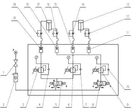
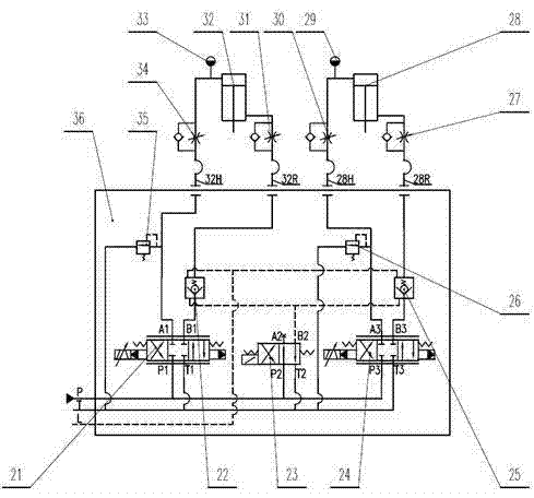
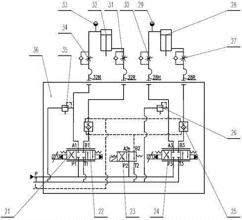
[0017] like figure 2 As shown, the hydraulic control circuit of the ironing roller device of the present invention includes a first hydraulic cylinder 32 and a second hydraulic cylinder 28 for driving the ironing roller, and the first hydraulic cylinder 32 and the second hydraulic cylinder 28 are arranged on the first hydraulic cylinder 32 and the second hydraulic cylinder 28 respectively. The first pressure sensor 33 and the second pressure sensor 29, and the first servo valve 21, the second servo valve 24 and the electromagnetic switch connected between the first hydraulic cylinder 32 and the second hydraulic cylinder 28 and the hydraulic oil source P through pipelines. Directional valve 23; the pipeline between the piston chamber and piston rod chamber of the first hydraulic cylinder 32 and the first serv...


PUM


Abstract

The invention discloses a hydraulic control loop for an ironing roller device, which comprises first and second hydraulic cylinders for driving an ironing roller, first and second pressure sensors arranged on the first and second hydraulic cylinders respectively, and a first servo valve, a second servo valve and an electromagnetic reversal valve which are connected among the first and second hydraulic cylinders and a hydraulic oil source by pipelines. The hydraulic control loop for the ironing roller device can accurately control the ironing pressure of the ironing roller, has high control accuracy, fast response speed, remarkable strip ironing effect and better quality, greatly increases the speed of a unit and increases the finished product ratio of the strip.

Description

technical field [0001] The invention belongs to the technical field of control of a coiler ironing device of an aluminum strip and foil rolling mill and a coiling unit, and in particular relates to a hydraulic control circuit of an ironing roller device. Background technique [0002] In the non-ferrous metal processing industry, with the increase of the operating speed of the aluminum strip and foil rolling mill and the coiling unit, during the coiling process of the aluminum strip and foil, due to air ingress, the coil will bulge, shrink and uncoil, and the strip will be seriously damaged. The shape of the plate increases the production loss and the difficulty of processing the next process. In order to avoid the above phenomena, the common practice is to limit the rolling speed of the strip, and as a result, the production capacity of the rolling mill cannot be fully utilized. In order to solve the above problems, the key factors are found out in combination with the proc...

Claims


Application Information

Patent Timeline
Patent Type & Authority Applications(China)
IPC IPC(8): B21B15/00B21C47/26F15B11/16
Inventor 韩吕昌
Owner CHINA NON-FERROUS METALS PROCESSING TECH CO LTD
Why Eureka
Try Eureka