Workpiece conveying system applied to automobile welding line

A conveying system and welding line technology, applied in conveyors, conveyor objects, mechanical conveyors, etc., can solve the problem of low utilization rate of conveying line equipment, achieve high production efficiency, low comprehensive investment cost, and ensure start-up rate. Effect

Active Publication Date: 2012-04-11
CHERY AUTOMOBILE CO LTD
View PDF6 Cites 41 Cited by
  • Summary
  • Abstract
  • Description
  • Claims
  • Application Information

AI Technical Summary

Problems solved by technology

However, since multiple new models of OEMs often need to be produced on the same line, the conveyor line suitable for a single model gradually shows some disadvantages. This "one-t

Method used


Image

  • Workpiece conveying system applied to automobile welding line
  • Workpiece conveying system applied to automobile welding line
  • Workpiece conveying system applied to automobile welding line

Examples


Embodiment 1

[0029] The specific implementation of the continuous and uninterrupted transportation scheme of two fixture trolleys for a single A model is as follows:

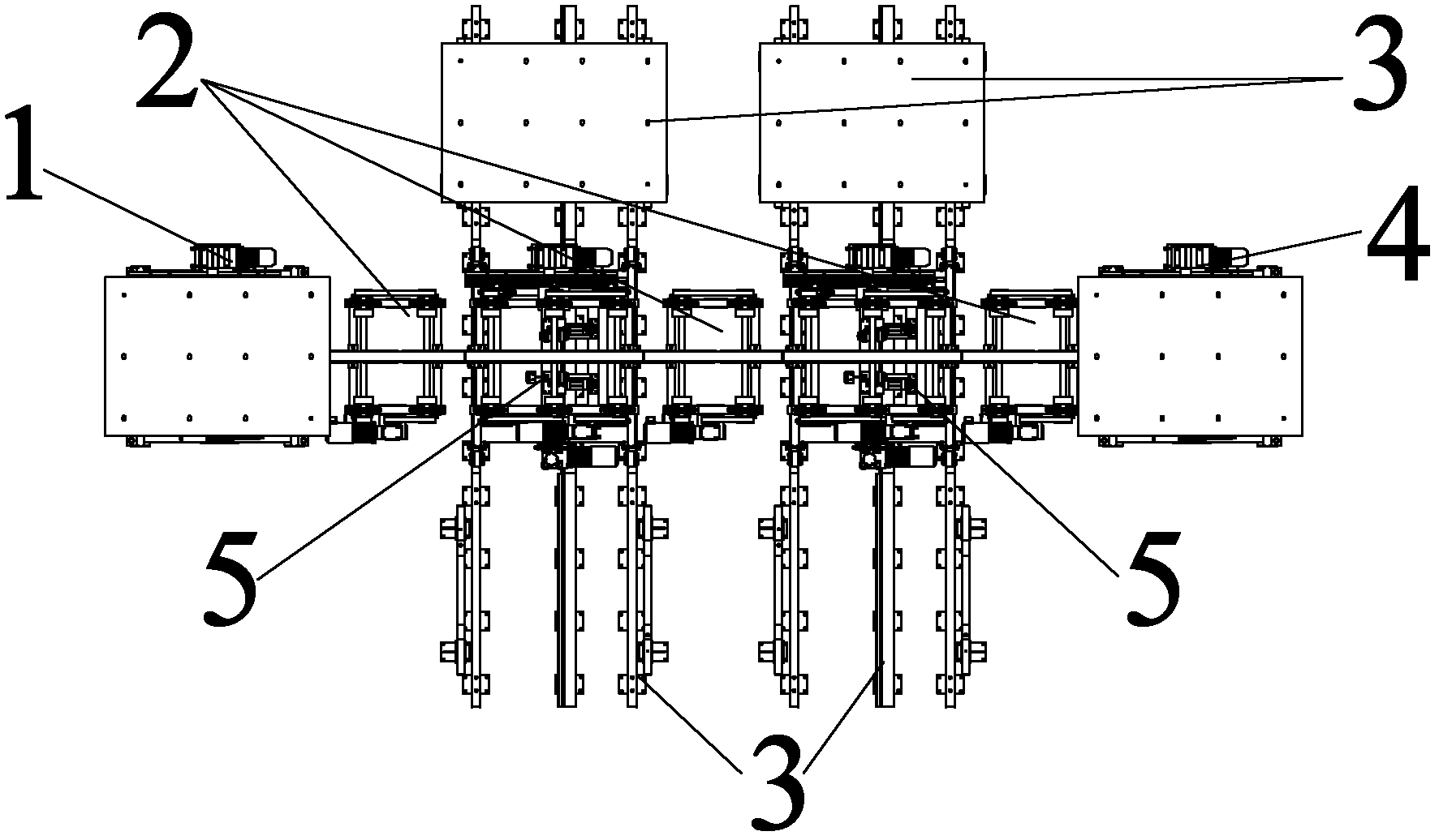
[0030] like Figure 4 As shown, there are two fixture trolleys A1 and fixture trolley A2, two fixture trolley switching devices 5, three corresponding transition devices 2, and four fixture trolley storage devices 3. When the fixture trolley A2 at the welding station performs welding operations, the fixture trolley A1 at the loading station can perform loading operations while the fixture trolley A2 is welding.

[0031]When the loading operation of the fixture trolley A1 is manually completed in the loading station, if the welding of the fixture table and fixture trolley A2 at the welding station has not been completed, then the lifting and rolling bed of the loading station will put the fixture trolley A1 Lifting, the jig trolley A1 breaks away from the jig fixing mechanism of the loading device 1, and then the jig trolley...

Embodiment 2

[0035] The switching of the respective fixture trolleys of the two different models A and B is implemented as follows:

[0036] like Figure 5 to Figure 8 As shown, on this workpiece conveying system, there are fixture trolley A1 and fixture trolley A2 belonging to model A, and fixture trolley B1 and fixture trolley B2 belonging to model B. According to the production task preparation, the fixture trolley switching device 5 The jig trolley storage device 3 on both sides, the jig trolley storage device 3 on one side is used to store the jig trolley of the A model, and the jig trolley storage device 3 on the other side is used to store the jig trolley of the B model. After the welding and assembly production of model A is completed, it is necessary to switch to the secondary assembly production of model B. like Figure 6 , at this time, the fixture trolley A2 completes the welding transfer and returns to the fixture trolley storage device 3 of the model A, and the fixture trol...


PUM


Abstract

The invention discloses a workpiece conveying system applied to an automobile welding line. The system comprises a fixture trolley matched with a conveyed workpiece, a workpiece feeding device, a welding transfer device, fixture trolley storage devices and fixture trolley switching devices, wherein the workpiece feeding device and the welding transfer device are arranged in a straight line; the fixture trolley switching devices are arranged in a middle area between the workpiece feeding device and the welding transfer device; the fixture trolley storage devices are arranged on two sides of each fixture trolley switching device; and the fixture trolley switching devices can transfer the workpiece conveyed on the workpiece feeding device and the welding transfer device to the fixture trolley storage devices. Through the technical scheme, secondary delivery warehouse assemblies and front and back bottom plates of various models can be conveyed and produced on the same line according to a process requirement, various models can be produced on the same automobile welding line, different models are quickly and flexibly switched, production efficiency is improved, and the requirement of the operating rate of equipment can be met to the greatest extent.

Description

technical field [0001] The invention relates to auxiliary process equipment for automobile manufacturing, in particular, the invention relates to a workpiece conveying system applied on an automobile welding line. Background technique [0002] At present, in the welding process of automobiles, for the welding and transportation of the secondary sub-assemblies such as the side wall, floor, and engine room of a certain model, the main engine manufacturers generally adopt a single model transportation mode, that is, a single model is used in the welding production line. Each vehicle type corresponds to a conveying scheme of a conveying line. However, since multiple new models of OEMs often need to be produced on the same line, the conveyor line suitable for a single model gradually shows some disadvantages. This "one-to-one" conveying solution cannot meet the current flexible production of multi-model mixed lines At the same time, it may also cause the problem of low utilizati...

Claims


Application Information

Patent Timeline
IPC IPC(8): B23K37/00B65G37/00B65G47/52
Inventor 李建收倪宝薛盛智周朴关伟
Owner CHERY AUTOMOBILE CO LTD
Why Eureka
Try Eureka