Automatic rolling and blanking mechanism

A blanking mechanism and rolling technology, which is applied in the direction of conveyor objects, transportation and packaging, can solve the problem of wasting energy and occupying space, and achieve the effect of saving energy consumption.

Inactive Publication Date: 2012-04-11
WUXI JIANGSU WEIFENG PRINTING MACHINE
View PDF0 Cites 0 Cited by
  • Summary
  • Abstract
  • Description
  • Claims
  • Application Information

AI Technical Summary

Problems solved by technology

[0004] The technical problem to be solved by the present invention is to overcome the problem that the blanking mechanism of the tongue depressor in the prior art uses at least two motors to realize the blanking function, thereby wasting energy and occupying a large space, and provides an automatic Rolling blanking mechanism

Method used


Image

  • Automatic rolling and blanking mechanism
  • Automatic rolling and blanking mechanism

Examples


Embodiment Construction

[0011] The preferred embodiments of the present invention will be described below with reference to the accompanying drawings. It should be understood that the preferred embodiments described here are only used to illustrate and explain the present invention, and are not used to limit the present invention.

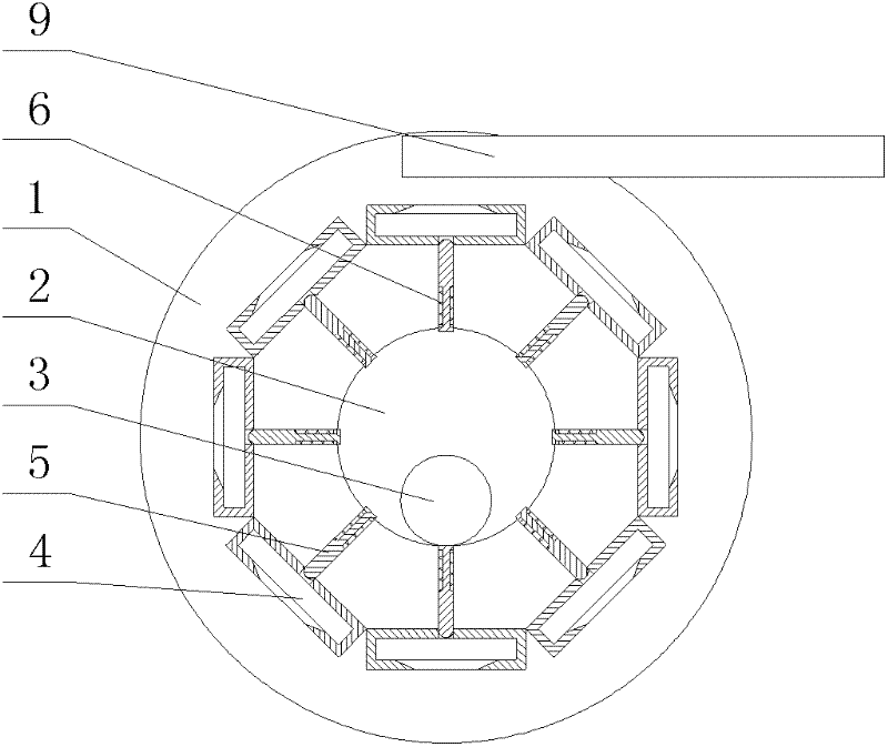
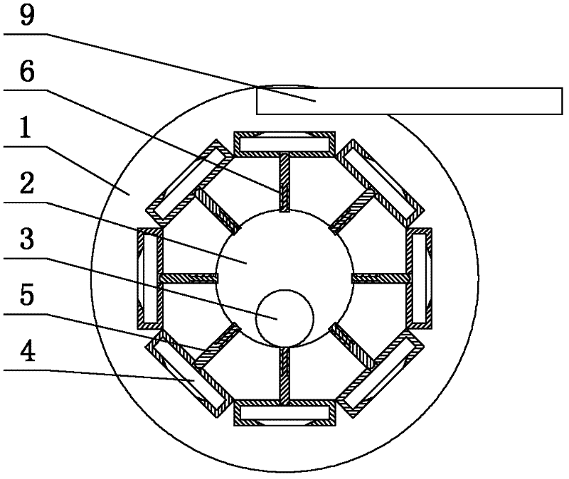
[0012] Such as figure 1 As shown, the automatic rolling blanking mechanism of the present invention includes an octagonal rolling shell 1. The center of the rolling shell 1 is a cylindrical hollow 2 and a roller 3 is placed in the center of the shell. The diameter of the roller 3 is less than half of the cylindrical hollow 2. A container 4 is provided on each side of the rolling shell 1, and corresponding to each container 4, a pressure is provided on the side of the cylindrical hollow. The material rod 5 is slidably installed in the sliding hole inside the container 4, and a return spring 6 is installed on the material pressure rod 5, one end of the material pressure rod 5 ...


PUM


Abstract

The invention relates to an automatic rolling and blanking mechanism, which comprises an octagonal rolling shell; a cylindrical hollow is formed in the center of the rolling shell and a rolling column is placed in the center of the shell; the diameter of the rolling column is smaller than half of the cylindrical hollow; a receiving box is arranged on each side surface of the rolling shell; a pressing rod is arranged on the side surface of the cylindrical hollow of the shell corresponding to each receiving box; the pressing rod is slidingly mounted in a sliding hole inside of the receiving box and is installed with a return spring; and one end of the pressing rod is extended to the inner part of the receiving box, while the other end of the pressing rod is connected with the cylindrical hollow. The rolling of the rolling column is pushed by rolling of the rolling shell, so that only a motor needs to drive the rolling shell to realize the aim of blanking, and the energy consumption can be greatly reduced in comparison with the conventional blanking mechanism which realizes the blanking action by using at least two motors.

Description

Technical field [0001] The invention relates to an automatic rolling and blanking mechanism, which belongs to the technical field of production equipment for commonly used medical device tongue depressors. Background technique [0002] At present, the tongue depressor only uses more traditional production equipment. In this technical field, after searching, it was found that domestic technical websites could not find newly developed technical information, including the official website of the State Intellectual Property Office and China Machinery Net. Therefore, it can be generally considered that at least domestic equipment manufacturers have invested little in the research and development of tongue depressors or simply engaged in the production of traditional equipment, and in response to the technical problems existing in traditional equipment, they have not proposed good solution. [0003] The existing tongue depressor blanking mechanism adopts a mechanical transmission metho...

Claims


Application Information

Patent Timeline
IPC IPC(8): B65G47/74B65G47/04
Inventor 吴伟平
Owner WUXI JIANGSU WEIFENG PRINTING MACHINE
Why Eureka
Try Eureka