

Gyro-type dynamic self-balancing pan-tilt
A self-balancing, gyroscopic technology, used in motor vehicles, machines/stands, supporting machines, etc., can solve problems such as affecting the shooting quality of shooting equipment and insufficient stability of the gimbal, and reduce the diameter and weight. , the effect of low energy consumption
- Summary
- Abstract
- Description
- Claims
- Application Information
AI Technical Summary
Problems solved by technology
Method used
Image

Examples
Embodiment 1
[0036] Such as figure 1 Shown is an embodiment of the present invention, a gyro-type dynamic self-balancing two-axis pan-tilt, including a frame assembly, a motor assembly, a control assembly and a shooting device 1 . The frame assembly includes a first bracket 2, a second bracket 4 and a third bracket 6, the shooting device 1 is fixed on the first bracket 2, the first bracket 2 and the second bracket 4 are rotated, the second bracket 4 and the third bracket 6Turn to set. The shape of the shooting device 1 is not limited to figure 1 The square shown in , can also be circular, ellipsoidal or other shapes. The motor assembly includes a first motor 3 and a second motor 5. The first motor 3 directly drives the first bracket 2 to rotate around its axis of rotation relative to the second bracket 4. The second motor 5 directly drives the second bracket 4 around its axis of rotation relative to the first bracket. Three supports 6 rotate. The power source provided in this embodimen...
Embodiment 2
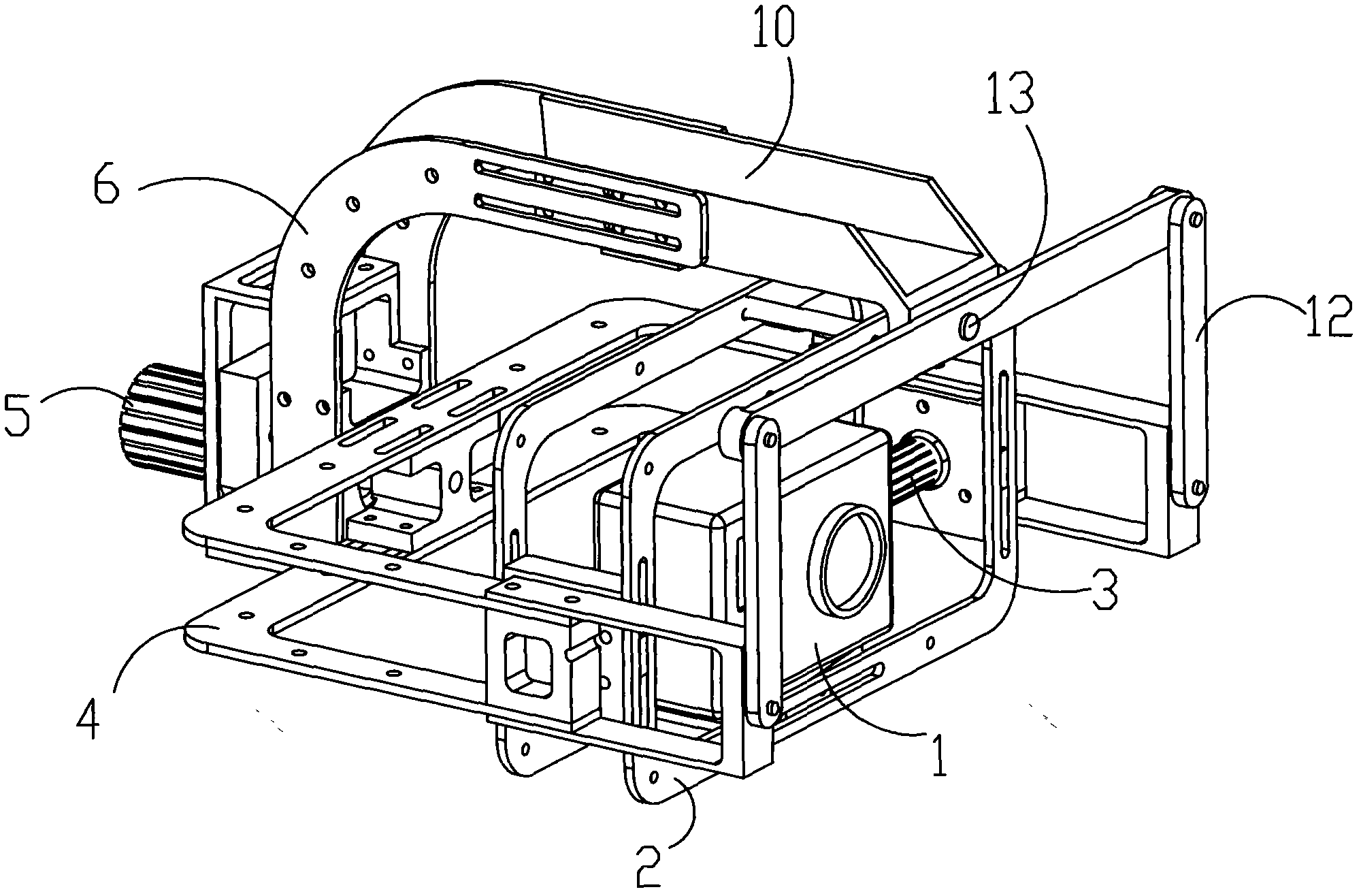
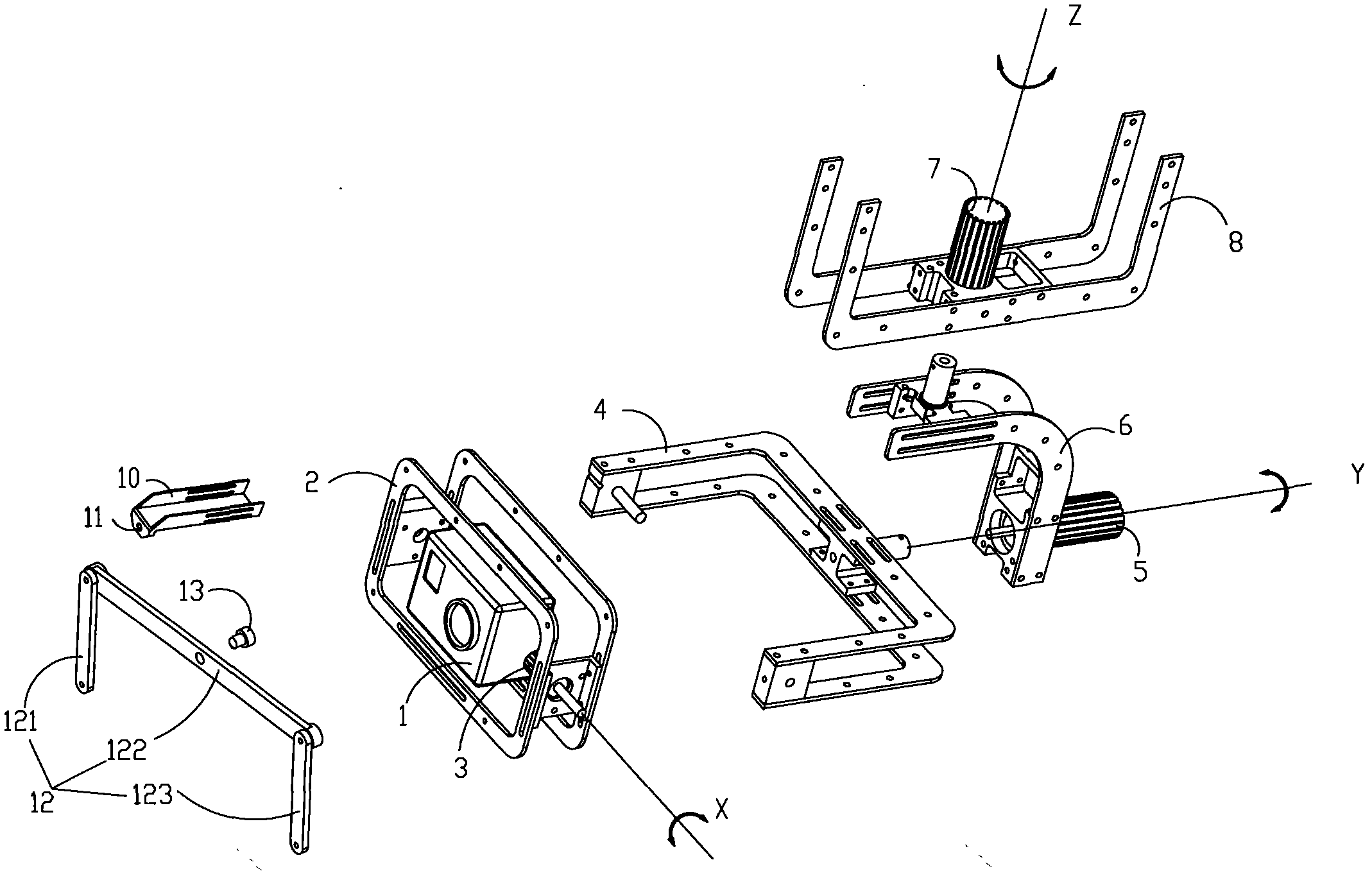
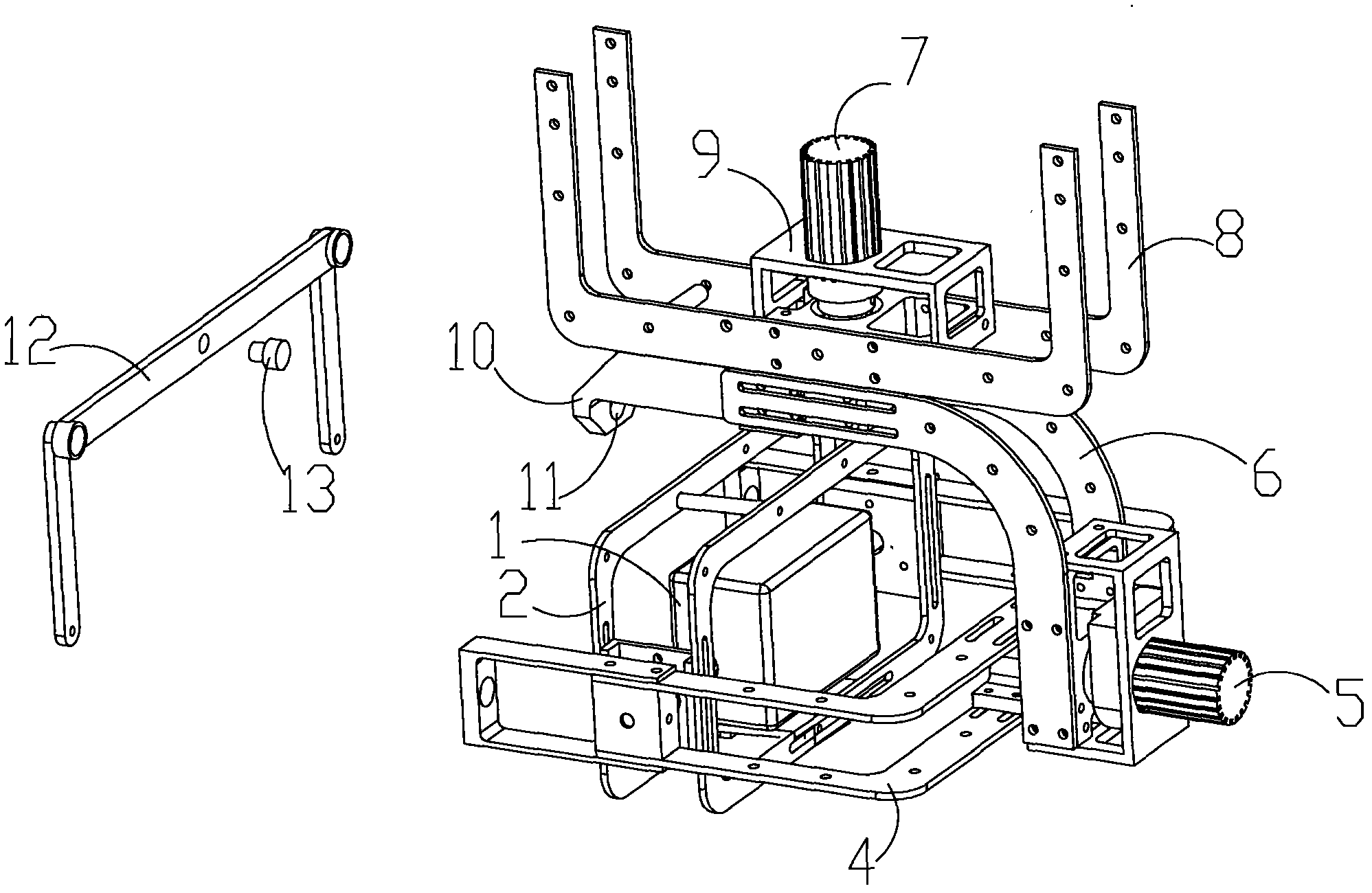
[0046] Such as Figure 2-Figure 6 As shown, another embodiment provided by the present invention is a gyro-type dynamic self-balancing three-axis pan-tilt, which includes a frame assembly, a motor assembly, a control assembly and a photographing device 1 . Such as figure 2 As shown, the frame assembly includes a first bracket 2, a second bracket 4, a third bracket 6 and a connecting bracket 8 for external fixing. The shooting device 1 is fixed on the first bracket 2. In order to realize the rotation of the shooting device 1 along the X axis (that is: the rotation axis of the first bracket 2), the first bracket 2 and the second bracket 4 are rotated. This rotation structure can realize The head up or down of the shooting device 1 rotates. In order to adapt to the left or right tilt of the carrier, the shooting device 1 correspondingly rotates to the left or right. In order to ensure the stability of the photo or video, such as Figure 5 , Figure 6 As shown, the second bra...
Embodiment 3
[0057] On the basis of Embodiment 1 and Embodiment 2, the difference of this embodiment is that the fastener 13 is replaced by a fourth motor, and the second connecting rod 122 of the connecting rod member 12 is directly driven by the fourth motor. Three supports 6 rotate. Here, the link member 12 will drive the second bracket 4 to rotate accordingly, so the fourth motor can assist the second motor 5 . It can be understood that the fourth motor can also replace the second motor 5 as the power source for the rotation of the second support 4 relative to the third support 6. At this time, the second motor 5 is not needed at all, and the motor assembly only needs the first motor 3, the third Motor 7 and the fourth motor.
PUM
 Abstract
Description
Claims
Application Information