

Method for Producing Non-Putrescible Sludge and Energy and Corresponding Plant
- Summary
- Abstract
- Description
- Claims
- Application Information
AI Technical Summary
Benefits of technology
Problems solved by technology
Method used
Image

Examples
first embodiment
7.4. Example of a Process According to the Invention
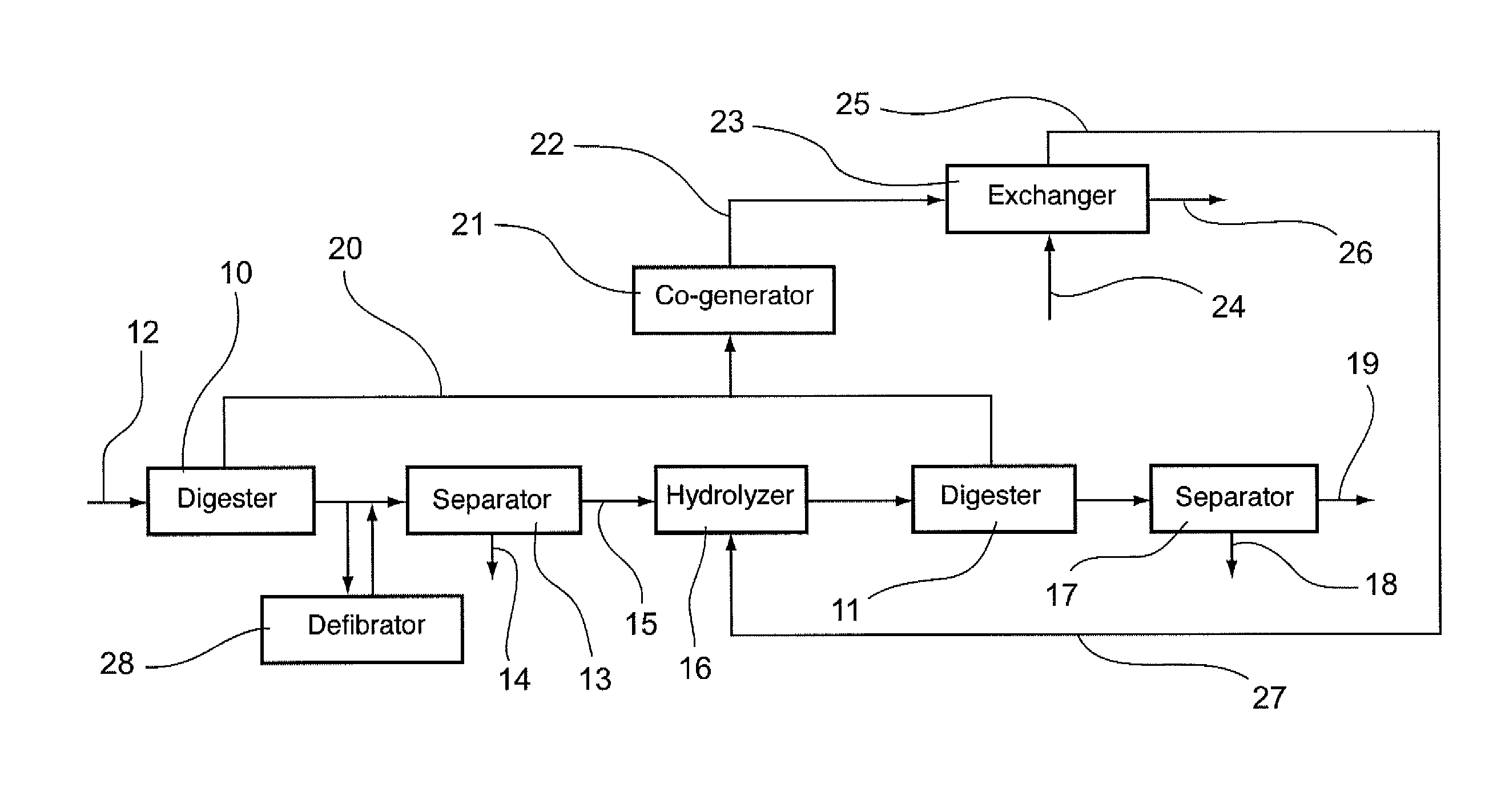
[0142]Referring to FIG. 1, a first embodiment is presented of a process for treating sludges according to the invention.
[0143]In this process, sludges to be treated are conveyed in a primary digester 10 so that they undergo a step of primary digestion. In this embodiment, the duration of this digestion is about 10 days. In alternative embodiments, it could range from 5 to 15 days.
[0144]During this digestion, there is:[0145]a reduction of the fermentable fraction of the sludges and therefore a reduction of the dry matter to be treated;[0146]a biological hydrolysis of a part of the non-fermentable minerals (such as nitrogen and phosphorous);[0147]an elimination of a large quantity of sugars contained in the sludges (this aspect can clearly be seen in FIGS. 3 and 4 which illustrate the sugar content of the sludges respectively before and after the implementation of the first digestion);[0148]the generation of low bio-degradable or non...
second embodiment
7.5. Example of the Process According to the Invention
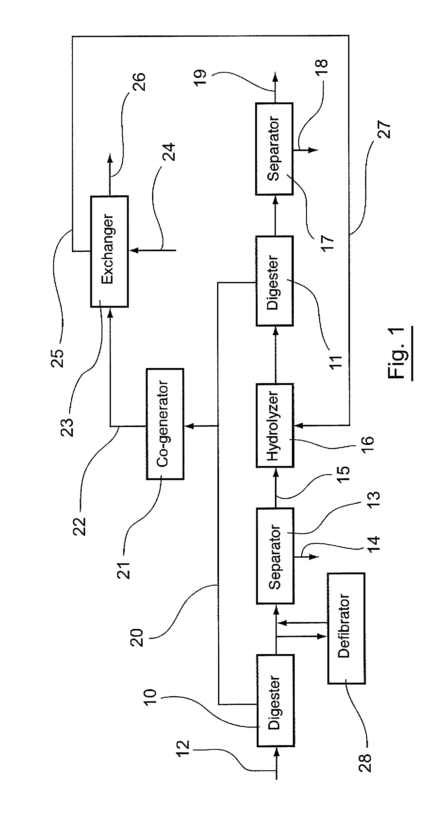
[0182]Referring to FIG. 2, a second embodiment of a sludge-treatment process according to the invention is presented.
[0183]In this process, sludges to be treated are conveyed into a digester 30 so that they undergo a step of primary digestion for about 10 days. In alternative embodiments, the step could range from 5 to 15 days.
[0184]During this primary digestion, there is:[0185]a reduction of the fermentable fraction of the sludges and therefore a reduction of the dry matter to be treated;[0186]a biological hydrolysis of a part of the non-fermentable minerals (such as nitrogen and phosphorous);[0187]an elimination of a large quantity of sugars contained in the sludges;[0188]the generation of low bio-degradable or non-biodegradable soluble organic matter such as high COD matter and refractory nitrogen;[0189]the solubilization of volatile fatty acids.
[0190]At the end of this digestion process, the fermentable fraction of the sludge...
PUM
 Abstract
Description
Claims
Application Information