
Gear and thin-wall disc combined type coupling

A combined, coupling technology, applied in the direction of coupling, elastic coupling, mechanical equipment, etc., can solve the problems that the rotation speed cannot meet the requirements, the coupling requirements are urgent, etc., and achieve small acting torque and force, The effect of high speed and easy adjustment

Inactive Publication Date: 2012-04-11
XI AN JIAOTONG UNIV
View PDF5 Cites 7 Cited by
  • Summary
  • Abstract
  • Description
  • Claims
  • Application Information

AI Technical Summary

Problems solved by technology

However, the speed of the existing couplings, such as gear couplings and diaphragm couplings, is far from meeting the requirements. Therefore, the high-speed rotor has increasingly urgent requirements for couplings.

Method used


Image

  • Gear and thin-wall disc combined type coupling
  • Gear and thin-wall disc combined type coupling
  • Gear and thin-wall disc combined type coupling

Examples


Embodiment Construction

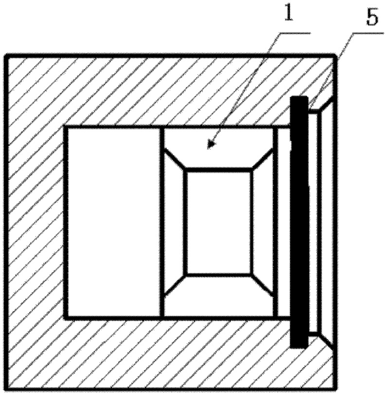
[0019] The structural principle and working principle of the present invention will be further described in detail below in conjunction with the accompanying drawings.

[0020] see figure 1 , figure 2 and image 3 , a gear-thin-walled disc combined coupling, including an inner gear 1, the inner gear of the inner gear 1 is connected to the outer gear sleeve at the beginning of the intermediate shaft 2, and the inner gear 1 is cold-pressed or shrink-fitted Cooperate with the end of the torque input shaft 3, the cylindrical thin wall on the thin disc at the end of the intermediate shaft 2 is interference fit with the initial end of the torque output shaft 4, the starting end and the end of the intermediate shaft 2 are connected by a thin rod, and the internal teeth The gear meshing between the internal teeth of the ring 1 and the external gear sleeve of the intermediate shaft 2 is lubricated by a lubricating sealing device 5 .

[0021] The tooth shape of the outer gear bushin...


PUM


Abstract

A gear and thin-wall disc combined type coupling comprises an internal gear ring. An internal gear of the internal gear ring is connected with an external gear shaft sleeve at the starting end of an intermediate shaft. The internal gear ring is matched with the tail end of a torque input shaft. The thin-wall cylinder on the thin-wall disc at the tail end of the intermediate shaft is in interference fit with the initial end of a torque output shaft. The starting end and the tail end of the intermediate shaft are connected by a thin rod. When the torque input shaft rotates, the internal gear ring rotates and drives the external gear shaft sleeve on the intermediate shaft to rotate, then the torque transmission is realized through the interference fit of the thin-wall cylinder on the intermediate shaft and the torque output shaft. When the torque input shaft and the torque output shaft are not aligned, the internal gear ring and the external gear shaft sleeve on the intermediate shaft are slant, the thin rod on the intermediate shaft and the thin-wall disc are elastically deformed for the misalignment between the torque input shaft and the torque output shaft. The coupling has the characteristics that the high misalignment can be adjusted, and the torque can be transmitted at high rotating speed.

Description

technical field [0001] The invention belongs to the technical field of shaft connection of high-speed rotating machines, and in particular relates to a gear-thin-wall disc combined shaft coupling. Background technique [0002] With the continuous increase of the speed of modern large-scale rotor systems, the speed of some high-speed rotors has already exceeded 10,000 or even hundreds of thousands of revolutions per minute, and large multi-span rotor systems usually need to be connected by couplings to achieve work. The main role played by the shaft is the transmission of torque from the power input end to the power output end. [0003] Due to factors such as misalignment of bearings, installation errors, and thermal expansion of the rotors, absolute alignment of the rotors does not exist, and the movement of the rotors in a state of misalignment can cause mechanical vibration, wear of the bearings, deflection of the shaft, The friction between the rotor and the stator is ex...

Claims


Application Information

Patent Timeline
IPC IPC(8): F16D3/18
Inventor 耿海鹏冯圣戚社苗杨柏松虞烈
Owner XI AN JIAOTONG UNIV
Learn More