Portable rock mass structural plane direct shear test apparatus for field and indoor use

A technology of direct shear tester and structural surface, applied in the direction of applying stable shear force to test the strength of materials, instruments, scientific instruments, etc., can solve the problems of structural surface shear strength parameter error, disturbance, structural surface dislocation, etc. , to achieve the effect of eliminating human error, eliminating error angle and improving accuracy

Inactive Publication Date: 2012-04-11
CHINA UNIV OF GEOSCIENCES (WUHAN)
View PDF6 Cites 41 Cited by
  • Summary
  • Abstract
  • Description
  • Claims
  • Application Information

AI Technical Summary

Problems solved by technology

When completing the above operation steps, due to the visual error of the human eye, it is difficult to ensure the level of the structural surface
Through the statistical work of the measurement data of a large number of structural surface samples prepared by pouring, it is found that the prepared structural surface samples generally have an error angle (the angle between the structural surface and the horizontal plane), which is about 5°, and it is impossible to accurately make the structural surface and the horizontal plane. horizontal plane parallel
During the test, due to the influence of the error angle, the vertical pressure and horizontal pressure applied by the vertical and horizontal loading systems will produce stress decomposition at the structural surface. The actual stress on the structural surface is different from the measured stress value. Finally, the shear strength parameters of the structural surface obtained through the analysis of the test data will inevitably have errors
[0004] (2) Due to the problem of the mold itself, after demould

Method used


Image

  • Portable rock mass structural plane direct shear test apparatus for field and indoor use
  • Portable rock mass structural plane direct shear test apparatus for field and indoor use
  • Portable rock mass structural plane direct shear test apparatus for field and indoor use

Examples


Embodiment Construction

[0069] The present invention will be further described below in conjunction with example and accompanying drawing.

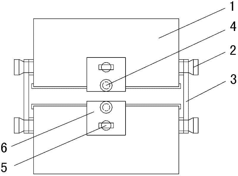
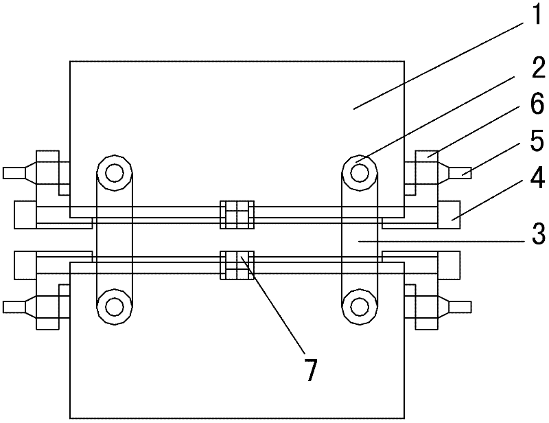
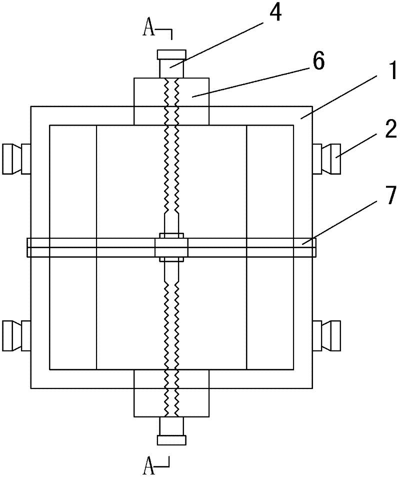
[0070] The present invention provides a portable on-site and indoor dual-purpose direct shear tester for rock mass structural surfaces (referred to as a direct shear tester), which is quite different from the existing portable direct shearer in terms of design ideas. The structure of the direct shear tester is as follows: Figure 1 to Figure 9 Shown: including sample preparation shear box and shear test device. Among them, the sample preparation and shearing box has a simple structure and is easy to operate. It combines the structural surface sample preparation and the shearing process into one, which optimizes the test process, ensures the accuracy of the test, eliminates the error angle of the structural surface sample preparation, and maximizes the accuracy of the test. The interference of human factors on the structural plane is greatly reduced. The design...


PUM


Abstract

The invention provides a portable rock mass structural plane direct shear test apparatus for field and indoor use. The apparatus comprises a sample preparation shear box and a shear test device. Specifically, the sample preparation shear box is mainly composed of a shear box housing, mould stripping pieces fixed by knobs and the shear box housing, and clamping pieces positioned at the ends of fixation screw rods that are mounted on the mould stripping pieces; the shear test device mainly consists of a shear test device outer frame, a vertical bearing plate, a horizontal pressure bearing instrument, sensors and jacks, with the vertical bearing plate mounted at the upper part of the shear test device outer frame and between a sensor and a jack, and the horizontal pressure bearing instrumentdisposed on a rolling shaft unit in the shear test device. Used in field or indoor rock mass structural plane direct shear tests, the apparatus of the invention can save sample preparation time, thusbeing suitable for rapid structural plane direct shear tests. The apparatus provided in the invention can improve the accuracy and convenience of structural plane direct shear tests, and has the advantages of simple structure, easy manufacturing, convenient operation and low cost, etc.

Description

technical field [0001] The invention relates to the field of rock mechanics tests, in particular to a novel portable structural surface direct shear instrument for obtaining structural surface shear strength parameters and deformation parameters in rock mechanics tests. Background technique [0002] The traditional portable structural surface direct shear tester has the following disadvantages: [0003] (1) When pouring, add a small amount of cement mortar to half of the sample mold, put the sample in the center, make the sheared surface 4-5mm higher than the frame of the sample mold, and make it horizontal; at the same time, keep the shear direction in line with the mold The direction of the long side of the frame is consistent, and then the cement mortar is injected to fill and compact. When completing the above operation steps, due to the visual error of the human eye, it is difficult to ensure the level of the structural surface. Through the statistical work of the mea...

Claims


Application Information

Patent Timeline
IPC IPC(8): G01N3/24G01N3/02G01N3/04
Inventor 唐辉明雍睿程昊黄磊倪卫达邹宗兴孙淼军
Owner CHINA UNIV OF GEOSCIENCES (WUHAN)
Why Eureka
Try Eureka