
Electromagnetic induction temperature field simulating device for abrasion test table of engine valve and housing

An electromagnetic induction and wear test technology, applied in the direction of measuring devices, strength characteristics, test wear resistance, etc., can solve the problems of uneven heating, difficult temperature control, difficult non-contact temperature measurement and control, etc., to solve slow heating, Energy consumption, no pollution, highly targeted effect

Inactive Publication Date: 2012-04-11
CHINA NORTH IND GRP NO 70 RES INST
View PDF3 Cites 7 Cited by
  • Summary
  • Abstract
  • Description
  • Claims
  • Application Information

AI Technical Summary

Problems solved by technology

Resistance wire heating can provide a stable temperature field and good controllability. However, it is difficult to realize the distribution of radial and axial resistance wires in the furnace cavity around the seat ring, and the resistance wire interface is easy to corrode and break. Therefore, Resistance wire electric heating has the disadvantages of large volume, short life, and poor observability; although gas injection heating can achieve the dual purposes of temperature simulation and atmosphere corrosion, the open gas injection heating has poor stability, uneven heating, difficult temperature control, and is harmful to the laboratory. environmental pollution
More importantly, it is difficult to achieve non-contact temperature measurement control by using resistance wire heating and gas injection, and the arrangement and sealing of thermocouples at the temperature measurement points of the workpiece heated for multiple rounds will also be a difficulty in realizing the temperature field simulation

Method used


Image

  • Electromagnetic induction temperature field simulating device for abrasion test table of engine valve and housing
  • Electromagnetic induction temperature field simulating device for abrasion test table of engine valve and housing
  • Electromagnetic induction temperature field simulating device for abrasion test table of engine valve and housing

Examples


Embodiment Construction

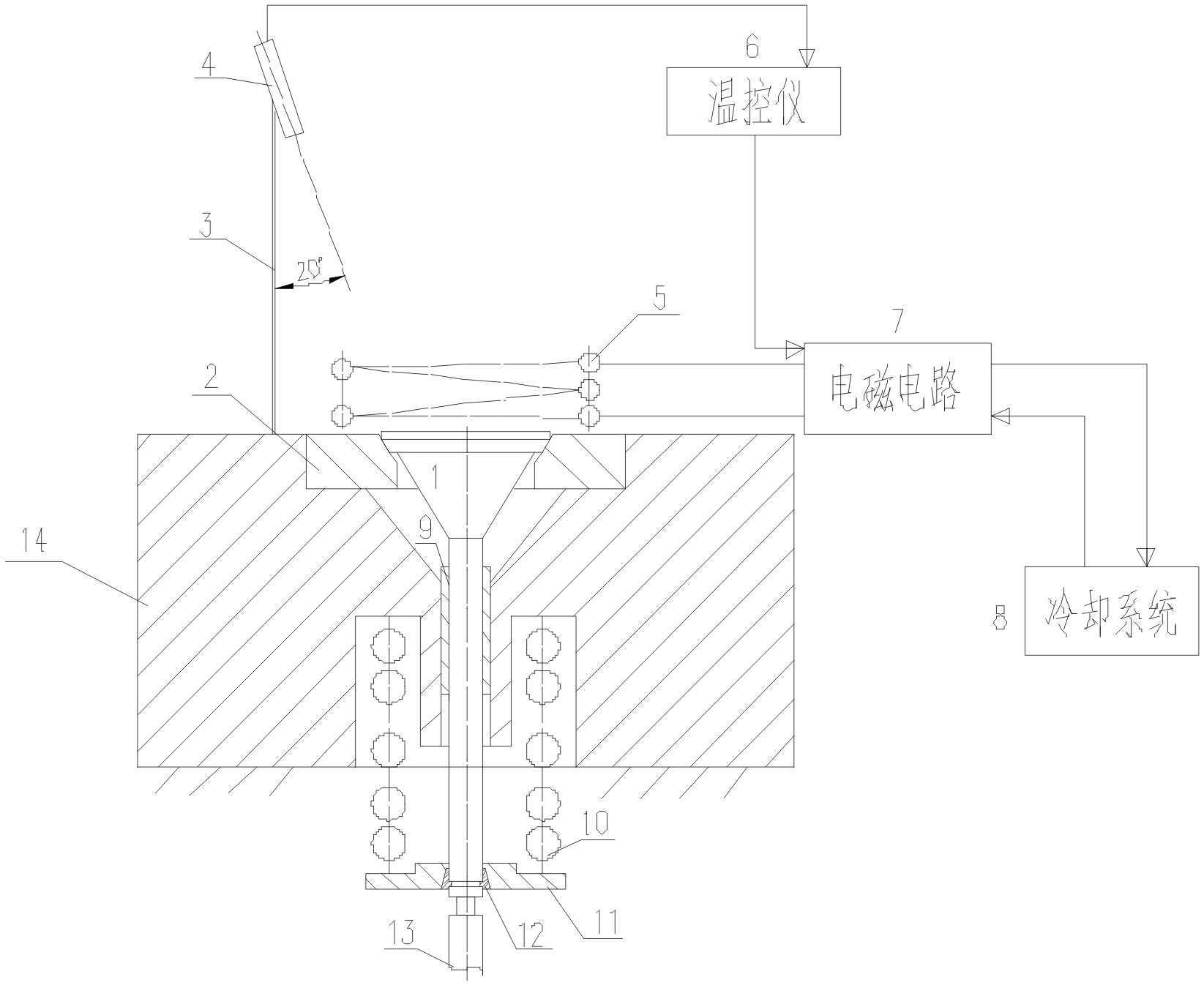
[0011] An electromagnetic induction temperature field simulation device for an engine valve and seat ring wear test bench, such as figure 1 As shown, it includes a valve 1, a seat ring 2, a bracket 3, an infrared sensor 4, a copper tube sensor 5, a temperature controller 6, an electromagnetic circuit device 7, a cooling device 8 and a test bench 9, and the valve 1 is set in the test On the stand 9, the seat ring 2 is arranged outside the valve 1, the copper tube inductor 5 is coaxially arranged with the seat ring 2 and its bottom surface is 5mm higher than the top surface of the seat ring 2, and the copper tube inductor 5 is connected with the electromagnetic circuit device 7, The infrared sensor 4 is set on the test bench 9 through the bracket 3 , the infrared sensor 4 is connected with the temperature controller 6 , the temperature controller 6 is connected with the electromagnetic circuit device 7 , and the electromagnetic circuit device 7 is connected with the cooling devic...


PUM


Abstract

The invention relates to an electromagnetic induction temperature field simulating device for abrasion test table of engine valve and housing. A valve (1) is arranged on a test table frame (9); the washer (2) is arranged out of the valve (1); a copper tube sensor (5) and the washer (2) are coaxially arranged and the bottom surface of the copper tube sensor is 5 mm higher than the washer (2); the copper tube sensor (5) is connected with an electromagnetic circuit device (7); an infrared sensor (4) is arranged on the test table frame (9) by a bracket (3); the infrared sensor (4) is connected with a temperature controller (6); the temperature controller (6) is connected with the electromagnetic circuit device (7); and the electromagnetic circuit device (7) is connected with a cooling device (8). The electromagnetic induction temperature field simulating device provided by the invention has features of small volume, long service life, good appearance, capability of realizing non-contact temperature measuring control, good heating stability, uniform heating, high heating pertinence, lower thermal load and capability of reducing pollution on laboratories.

Description

[0001] technical field [0002] The invention belongs to the field of engines, and in particular relates to an electromagnetic induction temperature field simulation device for an engine valve and seat ring wear test bench. Background technique [0003] The valve and seat ring are one of the important friction pairs of the engine. The operating life and reliability of the valve and seat ring determine the working performance, service life and output power of the engine to a certain extent. In recent years, as the power and reliability requirements of engines, especially diesel engines, have increased, the requirements for the friction pair of valves and seat rings have also increased accordingly. At present, for the temperature field simulation of the valve and seat ring friction and wear test system, there are only two implementation methods at home and abroad: resistance wire heating and gas injection. Resistance wire heating can provide a stable temperature field and goo...

Claims


Application Information

Patent Timeline
IPC IPC(8): G01N3/56G01N3/02
Inventor 陈闯彭海雄王小慧王根全孔冰
Owner CHINA NORTH IND GRP NO 70 RES INST
Learn More