
Adjustable non-overlapping clock signal generating method and generator

A clock generator and clock generation technology, applied in the direction of pulse generation, electric pulse generation, pulse processing, etc., can solve the problems of complex circuit structure and achieve the effect of simplifying the circuit

Inactive Publication Date: 2013-11-20
GUILIN UNIV OF ELECTRONIC TECH
View PDF7 Cites 0 Cited by
  • Summary
  • Abstract
  • Description
  • Claims
  • Application Information

AI Technical Summary

Problems solved by technology

However, in order to control the properties of non-overlapping clock pairs, DCOs, level shifters, and other digital circuits are used, making the circuit structure very complicated

Method used

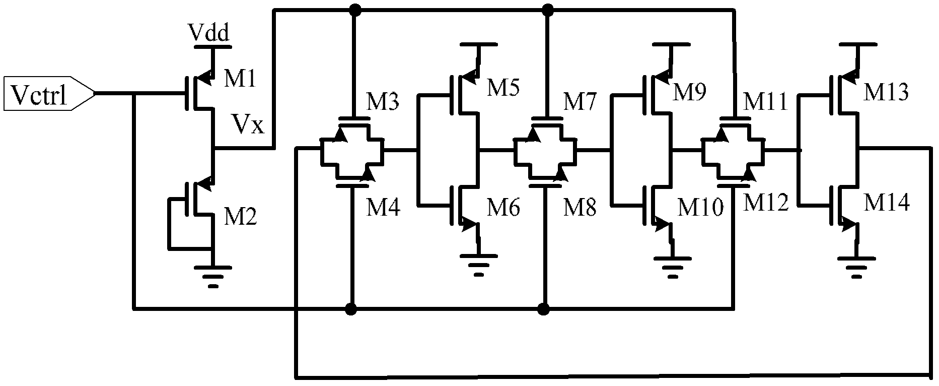

Image

  • Adjustable non-overlapping clock signal generating method and generator
  • Adjustable non-overlapping clock signal generating method and generator
  • Adjustable non-overlapping clock signal generating method and generator

Examples


Embodiment Construction

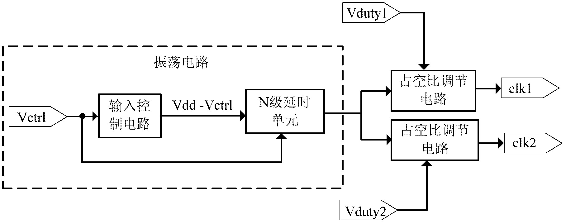
[0023] see figure 1 , an adjustable non-overlapping clock generation method of the present invention, comprising a square wave signal generation step and a square wave signal duty ratio adjustment step, the square wave signals generated by the oscillator circuit are respectively input into at least two duty ratio adjustment circuits, Each duty ratio adjustment circuit realizes the duty ratio adjustment of the square wave signal under the action of different duty ratio control signals, thereby obtaining at least two output signals with different duty ratios. These output signals with different duty ratios The output signal is the non-overlapping clock signal.

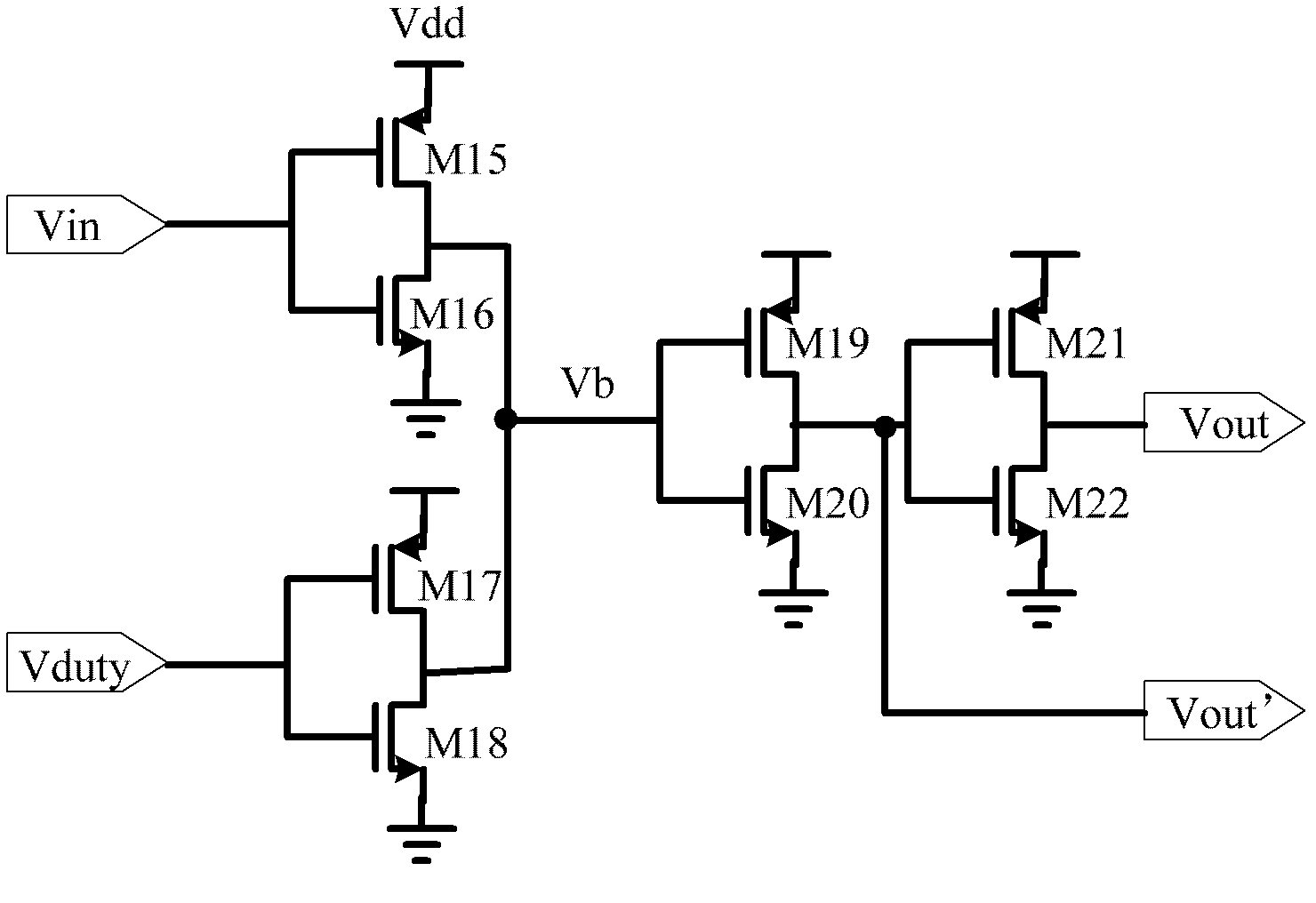
[0024] Each of the above-mentioned duty cycle adjustment circuits is composed of two input inverters and control inverters connected in parallel; the square wave signal input from the input inverter input is at the duty cycle Under the adjustment of the ratio control signal, change the inversion point of the input inver...


PUM


Abstract

The invention discloses an adjustable non-overlapping clock signal generating method and generator, and the method is characterized in that a square signal generated by an oscillating circuit is respectively output to at least 2 duty-ratio regulating circuits; duty-ratio regulation of the square signal is achieved by each duty-ratio regulating circuit through control signals with different duty ratios, thus output signals with different duty ratios of the at least two circuits are obtained, and the output signals with different duty ratios are non-overlapping clock signals. The adjustable non-overlapping clock signal generator provided by the invention has the characteristics of adjustable duty ratio and wide frequency output range.

Description

technical field [0001] The invention relates to a non-overlapping clock generator, in particular to an adjustable non-overlapping clock generation method and generator. Background technique [0002] Switched capacitor (SC) technology is a hot spot in CMOS VLSI. Switched capacitor circuits are not only widely used in analog signal processing (such as filters, switched capacitor DC-DC converters, and voltage comparators, etc.), but also penetrate into mixed-signal modules (such as analog-to-digital converters, Σ-Δ modulators, and sampling analog structure). The non-overlapping clock generator is used to control the switch of charging and discharging the capacitor, which is one of the core modules of the switched capacitor circuit. Traditional non-overlapping clock generator designs generally use NOR gates and inverter chains to form delay cells. Although researchers in the past have proposed different design methods for non-overlapping clock generators, most of the clock ci...

Claims


Application Information

Patent Timeline
Patent Type & Authority Patents(China)
IPC IPC(8): H03K5/15H03K3/017
Inventor 王卫东张学敏
Owner GUILIN UNIV OF ELECTRONIC TECH
Learn More