Method and device for controlling network flow as well as breakout gateway equipment

A network flow and flow control technology, applied in network connection, data exchange network, digital transmission system, etc., can solve the problems of poor user network experience and poor control effect, and achieve good effect and good network experience

Active Publication Date: 2012-04-11
BEIJING XINWANG RUIJIE NETWORK TECH CO LTD
View PDF3 Cites 11 Cited by
  • Summary
  • Abstract
  • Description
  • Claims
  • Application Information

AI Technical Summary

Problems solved by technology

[0008] Embodiments of the present invention provide a network traffic control method, device, and egress gateway device to solve the problems of poor control effect and poor user network experience when controlling network traffic in the prior art

Method used


Image

  • Method and device for controlling network flow as well as breakout gateway equipment
  • Method and device for controlling network flow as well as breakout gateway equipment
  • Method and device for controlling network flow as well as breakout gateway equipment

Examples


Embodiment 1

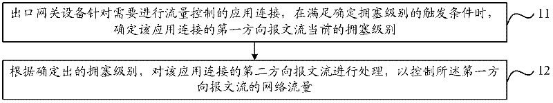
[0019] like figure 1 As shown, it is a schematic flow chart of the network traffic control method in the embodiment of the present invention, and its specific processing process is as follows:

[0020] In step 11, the egress gateway device determines the current congestion level of the packet flow in the first direction of the application connection when the trigger condition for determining the congestion level is satisfied for the application connection requiring flow control.

[0021] There may be multiple applications between the user in the local area network and the network device on the network side, and each application corresponds to at least one application connection. In Embodiment 1 of the present invention, the egress gateway device can select the user's application connection that needs to perform flow control. It is only necessary to perform network flow control on these application connections in the future, and it is not necessary to perform network flow contr...

Embodiment 2

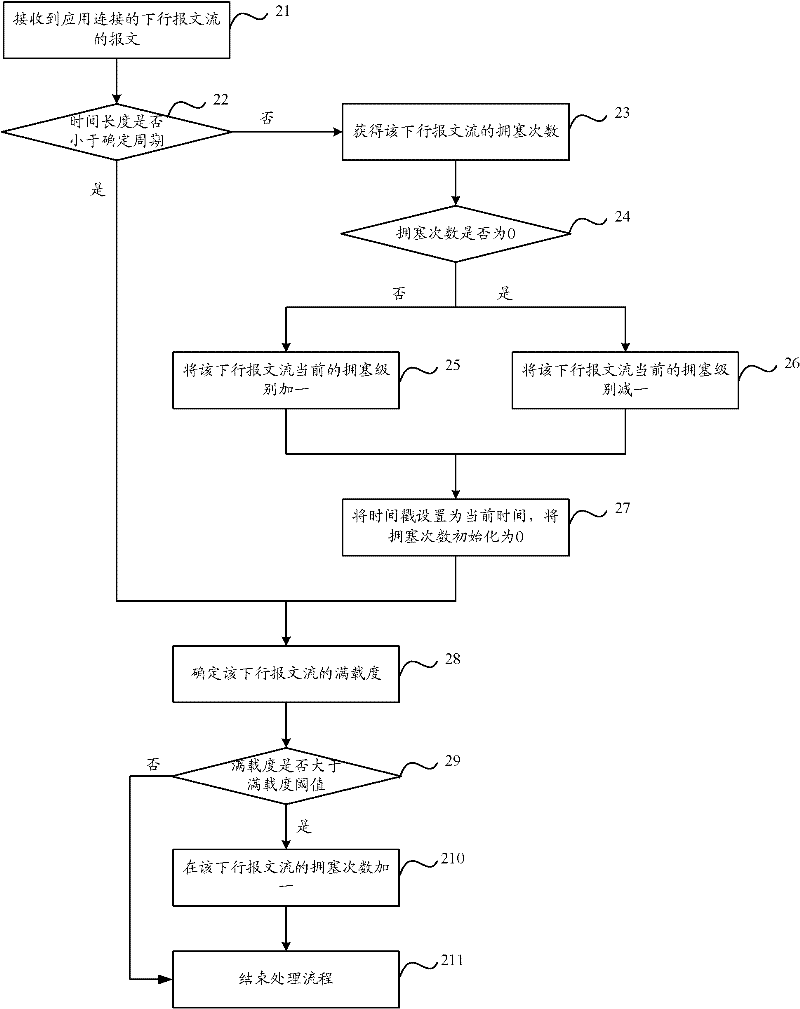
[0058] The egress gateway device wants to control the downlink network traffic connected to an application. The trigger condition for determining the congestion level is the receipt of downlink packets, and the downlink packet flow is comprehensively determined based on the full load and time of the downlink packet flow. The congestion level of the downlink packet flow is determined using the above-mentioned method of determining the full load based on the queue length, as follows figure 2 As shown, it is a schematic flow chart of the method for determining the congestion level of the downlink packet flow in Embodiment 2 of the present invention, and its specific processing flow is as follows:

[0059] Step 21, the egress gateway device receives the message of the downstream message flow of the application connection;

[0060] Step 22, the egress gateway device judges whether the time length between the current time and the time corresponding to the time stamp of the downlink...

Embodiment 3

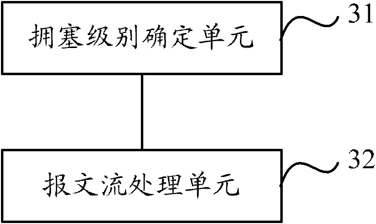
[0071] Corresponding to the network traffic control method proposed in Embodiment 1 of the present invention, Embodiment 3 of the present invention proposes a network traffic control device, the structure of which is as follows image 3 shown, including:

[0072] The congestion level determination unit 31 is configured to determine the current congestion level of the first direction packet flow of the application connection when the trigger condition for determining the congestion level is satisfied for the application connection requiring flow control;

[0073] The packet flow processing unit 32 is configured to process the packet flow in the second direction of the application connection according to the congestion level determined by the congestion level determination unit 31, so as to control the network traffic of the packet flow in the first direction, wherein , when the first direction is a downlink direction, the second direction is an uplink direction, and when the fi...


PUM


Abstract

The invention discloses a method and a device for controlling network flow as well as breakout gateway equipment. The method comprises: aiming at an application connection in need of flow control, the breakout gateway equipment determines the current congestion level of first-direction message flow for the application connection on the premise of meeting the trigger condition for determining the congestion level; and according to the determined congestion level, the breakout gateway equipment processes second-direction message flow for the application connection so as to control the network flow of the first direction message flow, wherein the second direction is an uplink direction when the first direction is a downlink direction, and the second direction is a downlink direction when the first direction is an uplink direction. By adopting the technical scheme of the invention, the problems of the prior art such as worse control effect and worse network experience of a user in the case of network flow control are solved.

Description

technical field [0001] The invention relates to the technical field of network flow control, in particular to a network flow control method, device and egress gateway equipment. Background technique [0002] The egress gateway device of the LAN is responsible for connecting the users in the LAN to the network side, and performing protocol conversion, routing selection, data exchange and other processing. When users in the LAN interact with the network side, they will occupy a certain amount of network bandwidth and generate a certain amount of network traffic. In order to prevent certain users from occupying more network bandwidth and affecting the message interaction between other users in the LAN and the network side , the egress gateway device generally controls the user's network traffic. [0003] In the prior art, the egress gateway device generally adopts the following two methods to control network traffic: [0004] (1) Directly limit the transmission rate of downli...

Claims


Application Information

Patent Timeline
Patent Type & Authority Applications(China)
IPC IPC(8): H04L12/56H04L12/66H04L12/825
Inventor 钟志强
Owner BEIJING XINWANG RUIJIE NETWORK TECH CO LTD
Why Eureka
Try Eureka