Check patentability & draft patents in minutes with Patsnap Eureka AI!

Rolling element screw device

A rolling element and lead screw technology, which is applied to transmissions, transmission parts, belts/chains/gears, etc., can solve the problems of time-consuming and labor-intensive replacement, hinder the heat dissipation of nut components, etc., and achieve easy replacement and easy maintenance in good condition. Effect

Inactive Publication Date: 2012-04-11
THK CO LTD
View PDF6 Cites 0 Cited by
  • Summary
  • Abstract
  • Description
  • Claims
  • Application Information

AI Technical Summary

Problems solved by technology

[0011] On the other hand, in the lubricating structure disclosed in Japanese Patent Application Laid-Open No. 2003-232427, although the lubricant box can be installed and detached from the nut member, when replacing the lubricant box, the above-mentioned connecting pipe must be temporarily removed from the lubricant box. Or the smear body is removed, and the connecting pipe is reassembled after the lubricant box is replaced, resulting in time-consuming and labor-intensive replacement
In addition, since the substantially C-shaped lubricant box covers almost the entire outer peripheral surface of the nut member, there is a possibility that heat dissipation of the nut member may be hindered.

Method used


Image

  • Rolling element screw device
  • Rolling element screw device
  • Rolling element screw device

Examples


Embodiment Construction

[0052] Hereinafter, the rolling element screw device of the present invention will be described in detail using the drawings.

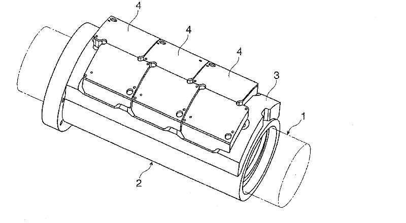
[0053] figure 1 It is an example showing that the present invention is applied to a ball screw device. This ball screw device includes: a screw shaft 1 in which rolling grooves for rolling balls as rolling elements are helically formed on an outer peripheral surface; a nut member 2 screwed to the screw shaft 1 by a plurality of balls; and A lubricant box 4 is mounted on the outer peripheral surface of the nut member 2 via a cover plate 3 . In addition, in figure 1 In , the above-mentioned screw shaft 1 is indicated by a dotted line.

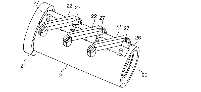
[0054] figure 2 It is a perspective view which shows the state which removed the said lubricant tank 4 and the cover plate 3 from the said nut member 2. The nut member 2 has a through hole 20 through which the screw shaft 1 is inserted, and is formed in a substantially cylindrical shape, and one end in the axial ...


PUM


Abstract

Provided is a rolling-element screw device which does not sacrifice a stroke distance of a nut member (2) although carrying a sufficient amount of lubricant, or hinder heat radiation of the nut member (2), and contributes to facilitation of a replacement operation of a lubricant tank (4). The rolling-element screw device includes: a large number of rolling elements (5); a screw shaft (1) having an outer periphery on which a rolling groove (10) for the large number of rolling elements (5) is helically formed; a nut member (2) which has a through-hole (20) through which the screw shaft (1) is passed and which is threadedly engaged with the screw shaft (1) through intermediation of the large number of rolling elements (5); a lubricant supply hole (29) formed through the nut member (2) from an outer peripheral surface of the nut member (2) to an inner peripheral surface of the nut member (2); a lubricant tank (4) mounted to the outer peripheral surface of the nut member (2) and comprising an accommodating chamber for lubricant; and a lubricant applying body (43) standing from the lubricant tank (4), and inserted into the lubricant supply hole (29) along with a mounting operation of the lubricant tank (4) with respect to the nut member (2), the lubricant applying body (43) having a leading end portion coming into contact with the rolling groove (10) of the screw shaft (1) so as to apply the lubricant.

Description

technical field [0001] The present invention relates to a rolling element screw device such as a ball screw or a roller screw, and more particularly to a rolling element screw device having a function of applying a lubricant to rolling grooves of a screw shaft. Background technique [0002] Rolling element screw devices such as ball screws and roller screws include: a screw shaft with rolling grooves for rolling elements such as balls and rollers spirally formed on the outer peripheral surface; The body is screwed to the nut member of the above-mentioned screw shaft. In addition, a loaded rolling groove opposite to the rolling groove of the screw shaft is formed on the inner peripheral surface of the nut member, and by connecting the rolling groove of the screw shaft and the loaded rolling groove of the nut member, On the other hand, the loaded raceways of the rolling elements are helically formed around the screw shaft. Next, when the screw shaft is relatively rotated wit...

Claims


Application Information

Patent Timeline
IPC IPC(8): F16H25/24F16H25/22
CPCF16H57/0497F16H25/2214Y10T74/18744Y10T74/19744Y10T74/19749Y10T74/19767
Inventor 宫原庄志齐藤秀生角野寿昭芳野雅彦咲山隆富樫勉谷和弘龟田绘里中村太
Owner THK CO LTD
Features
  • R&D
  • Intellectual Property
  • Life Sciences
  • Materials
  • Tech Scout
  • Unparalleled Data Quality
  • Higher Quality Content
  • 60% Fewer Hallucinations
Learn More