Forced casting cooling system

A technology of forced cooling and casting, applied in the field of cooling system, can solve the problem of increased floor space or space, and achieve the effect of saving floor space, improving cooling effect and shortening cooling time

Inactive Publication Date: 2012-04-18
DATONG RENHE CASTING
View PDF3 Cites 3 Cited by
  • Summary
  • Abstract
  • Description
  • Claims
  • Application Information

AI Technical Summary

Problems solved by technology

In short, because the existing production line does not have a good forced cooling system, the castings are designed to be transported out of the box, which greatly increases the floor area or space

Method used


Image

  • Forced casting cooling system
  • Forced casting cooling system
  • Forced casting cooling system

Examples


Embodiment Construction

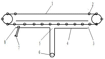
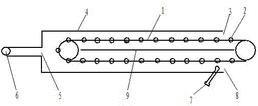
[0015] figure 1 It is a structural schematic diagram of the first technical solution of the casting forced cooling system; figure 1 As shown, the system includes a semi-sealed cover 4 with a cylindrical structure; the front and rear ends of the semi-sealed cover 4 are open structures, the opening at the front end is the entrance 3, and the opening at the rear end is the exit 8; the casting conveying line 1 passes through the entrance 3 And the outlet 8 passes through the semi-sealed cover 4. The middle part of the semi-sealed cover 4 of this system is provided with an air exhaust port 5, and the air exhaust port 5 is connected with an electric induced draft fan 6. The system is provided with a temperature sensor 7 at the outlet 8 of the semi-sealed cover 4, and the electrical signal of the temperature sensor 7 controls the speed of the electric induced draft fan through a frequency converter, thereby changing the exhaust air volume of the electric induced draft fan 6.

[001...


PUM


Abstract

The invention discloses a forced casting cooling system. In the forced casting cooling system, a section of semi-tight cover is enclosed on a casting conveying line; the semi-tight cover is provided with a suction port; and the suction port is communicated with a motor draught fan. Due to the adoption of the system, the casting cooling time can be greatly shortened, the length of the casting conveying line is reduced, the floor area is saved, and the casting cooling effect is improved; and the casting conveying production line can run normally, and the production is not influenced.

Description

technical field [0001] The invention relates to a cooling system, in particular to a casting forced cooling system. Background technique [0002] At present, in the foundry industry, the cooling of castings is always closely watched. In the process of conveying the castings after unpacking in various casting production lines, the common problem is that the design of the conveying line is very long, so that the castings can obtain a longer cooling time, so that the temperature of the castings can be lowered to the point where the next process can be operated. level, so that the next process cannot be produced normally. For this reason, some production conveying lines have to pass through the outside, and even need to add multiple blowers to blow air in order to obtain a better cooling effect. In short, because the existing production line does not have a good forced cooling system, the castings are designed to be transported out of the box, which greatly increases the floor...

Claims


Application Information

Patent Timeline
Patent Type & Authority Applications(China)
IPC IPC(8): B22D30/00
Inventor 周祚超
Owner DATONG RENHE CASTING
Why Eureka
Try Eureka