
Rod baffle heat exchanger

A baffle rod and heat exchanger technology, which is applied in the direction of heat exchanger shell, heat exchange equipment, lighting and heating equipment, etc., can solve the problems of large fluid flow resistance, vibration and wear of heat exchange tubes, leakage of heat exchange tubes, etc. Achieve the effect of not easy to deposit, eliminate lateral scour, and reduce shear stress

Inactive Publication Date: 2012-04-18
ACRE COKING & REFRACTORY ENG CONSULTING CORP DALIAN MCC +1
View PDF4 Cites 8 Cited by
  • Summary
  • Abstract
  • Description
  • Claims
  • Application Information

AI Technical Summary

Problems solved by technology

However, since the fluid needs to pass across the tube bundle many times, the scouring direction is changed repeatedly, and the scouring angle is roughly vertical, so the flow resistance of the fluid is very large, there is a flow dead zone locally, and it is easy to cause induced vibration, causing the heat exchange tube Vibration wear, which eventually leads to leakage of heat exchange tubes

Method used


Image

  • Rod baffle heat exchanger
  • Rod baffle heat exchanger
  • Rod baffle heat exchanger

Examples


Embodiment Construction

[0014] The device structure and working process of the baffle rod heat exchanger will be described in detail below through specific embodiments.

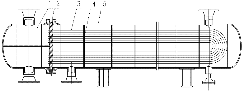
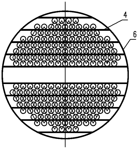
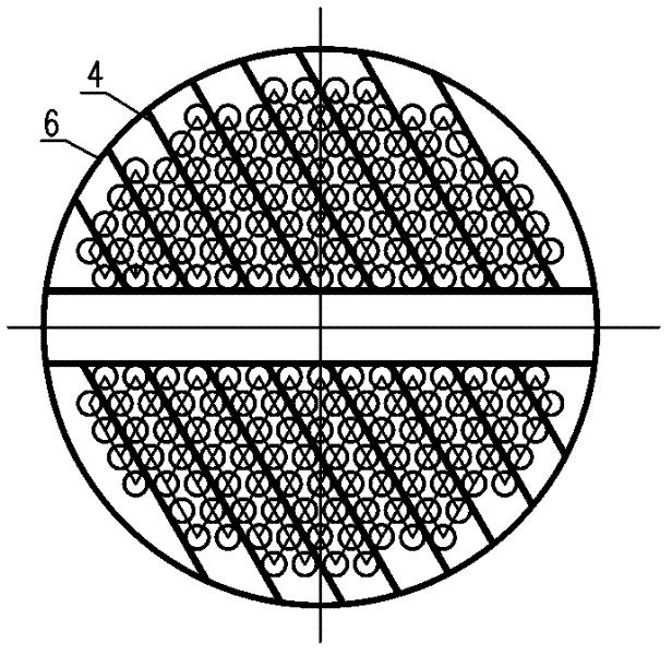
[0015] See figure 1 , Figure 2-a , Figure 2-b , Figure 2-c , Figure 2-d , one A baffle rod heat exchanger, including a tube box 1, a tube sheet 2, a heat exchange tube 3, a baffle rod 4, a shell 5, and a baffle ring 6, which are perpendicular to the axial direction of the shell 5 in the shell 5 A plurality of baffle grids are arranged at intervals in the direction of the baffle grid. The baffle grids are composed of mutually parallel baffle rods 4 welded on the baffle ring 6. The heat exchange tube bundle passes through the baffle rods 4. The diameter or thickness of the baffle rods It is exactly equal to the gap between two adjacent rows of heat exchange tubes; the direction of the baffle rods in the adjacently arranged baffle grids is different, so that every time the shell-side fluid passes through a baffle grid, a turb...


PUM


Abstract

The invention relates to a rod baffle heat exchanger for a benzene hydrogenation refining process. The rod baffle heat exchanger comprises a tube box, a tube plate, a shell and heat exchange tubes. A plurality of blast fences are arranged at intervals in a direction vertical to the axial direction of the shell in the shell. The blast fence is formed by welding parallel rod baffles onto a baffle ring. A heat exchange tube bundle passes through the rod baffles. The extension directions of the rod baffles in adjacent blast fences are different, so that a turbulent flow is produced once every time when a shell-side fluid passes through a blast fence. The section of the rod baffle may be circular, rectangular or prismatic. By the heat exchanger, the shell-side fluid forms a longitudinal flow along the axial direction of the shell, so that transversal scouring to the heat exchange tube bundle is avoided, the shearing stress of the tube bundle and a support structure is effectively weakened, and the vibration and abrasion of the tube bundle are reduced; moreover, the structure also has a turbulent flow self-cleaning function, and fouling is difficult to deposit.

Description

technical field [0001] The invention relates to a coking and chemical equipment, in particular to a baffle rod type extraction raw material / lean solvent heat exchanger used in a benzene hydrogenation refining process. Background technique [0002] The extraction raw material / lean solvent heat exchanger is a heat exchanger that uses sulfolane to heat mixed hydrocarbon media. It uses baffles or support plates as the support structure of the tube bundle to increase the flow rate and force the fluid to cross flow multiple times according to the specified path. Through the tube bundle, the heat transfer coefficient of the shell side is improved. However, since the fluid needs to pass across the tube bundle many times, the scouring direction is changed repeatedly, and the scouring angle is roughly vertical, so the flow resistance of the fluid is very large, there is a flow dead zone locally, and it is easy to cause induced vibration, causing the heat exchange tube Vibration wear,...

Claims


Application Information

Patent Timeline
Patent Type & Authority Applications(China)
IPC IPC(8): F28F9/24
Inventor 闫勇段有龙
Owner ACRE COKING & REFRACTORY ENG CONSULTING CORP DALIAN MCC
Learn More