Optical path micro-adjustment device and method

A micro-adjustment and optical adjustment technology, applied in optical components, optics, instruments, etc., can solve the problems of light change, low precision, large error, etc., and achieve the effect of reducing production cost, improving the light path, and reducing the amount of light path change.

Inactive Publication Date: 2012-04-18
INNOLIGHT TECHNOLOGY (SUZHOU) LTD
View PDF4 Cites 2 Cited by
  • Summary
  • Abstract
  • Description
  • Claims
  • Application Information

AI Technical Summary

Problems solved by technology

[0007] The purpose of the present invention is to overcome the deficiencies in the prior art, and provide a device and method for fine-tuning the optical path, which aims to effectively solve the prob...

Method used


Image

  • Optical path micro-adjustment device and method
  • Optical path micro-adjustment device and method
  • Optical path micro-adjustment device and method

Examples


Embodiment Construction

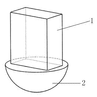
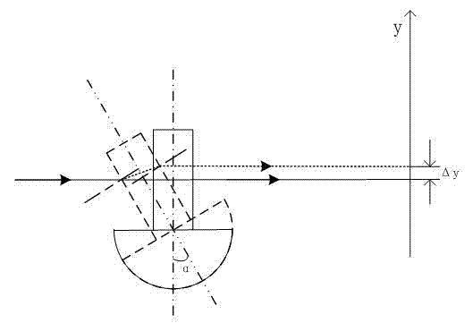
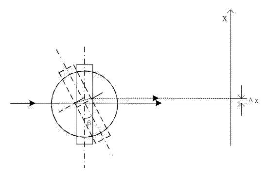
[0022] The optical path micro-adjustment device includes an optical adjustment plate and an adjustment cap. The optical adjustment plate is made of light-transmitting materials, including various glass materials, and its shape is a rectangular parallelepiped or a wedge. At least one side is coated with an anti-reflection film. The anti-reflection coating may not be coated; the adjustment cap is hemispherical, which is used to support the optical adjustment plate, and the hemispherical support is beneficial to the adjustment of the two-dimensional optical path micro-adjustment device for swinging back and forth and turning left and right.

[0023] Such as figure 1 As shown, the optical adjustment plate 1 is a cube, and the lower hemisphere is the adjustment cap 2. The adjustment cap 2 is made of metal, glass and other materials. The optical adjustment plate 1 and the adjustment cap 2 can be separated into two, bonded or welded together, The two can also be integral structures. ...


PUM


Abstract

The invention relates to an optical path micro-adjustment device. The device comprises at least one optical adjustment plate and an adjustment cap for supporting the optical adjustment plate, wherein the optical adjustment plate is a cuboid or a wedge-shaped body; and the adjustment cap is semispherical. An optical path micro-adjustment method comprises the following steps of: when the device is used for micro-adjustment of an optical path, placing the adjustment cap in a semispherical groove, and placing the optical adjustment plate at an optical path transmission position; operating the adjustment cap to ensure that the optical path micro-adjustment device is swung back and forth and rotated right and left; changing the angle between light rays and the incident surface of the optical adjustment plate; refracting the optical path through the optical adjustment plate by using a large-adjustment and small-variation effect of an optical lever to ensure that the optical path is changed in the XY direction; and when the optical path reaches an appropriate position, fixing the adjustment cap and the groove. By the device and the method, the problems of low adjustment accuracy of the optical path and difficulty in maintenance of the adjusted optical path are effectively solved; when a laser is coupled to an optical path adjustment process of optical fibers/waveguides, the device and the method have extremely high accuracy requirements on XY; and the optical path is extremely accurately adjusted finely by using the optical path micro-adjustment device.

Description

technical field [0001] The invention relates to an optical path micro-adjustment device, in particular to an optical path micro-adjustment device used in an optical module for coupling a laser to an optical fiber / waveguide. Background technique [0002] [0003] in L is the distance from the light source to the photosensitive screen; [0004] To adjust the thickness of the plate for optical; [0005] n The refractive index of the material used for the optical adjustment plate; [0006] Contents of the invention [0007] The purpose of the present invention is to overcome the deficiencies in the prior art, and provide a device and method for fine-tuning the optical path, which aims to effectively solve the problems of large errors, low precision, and changes in the optical path after adjustment in the traditional optical path adjustment, and can better Applied to the adjustment of various miniature optical paths. [0008] The purpose of the present invention is ...

Claims


Application Information

Patent Timeline
IPC IPC(8): G02B7/00G02B1/11
Inventor 李伟龙孙雨舟王攀施高鸿刘圣
Owner INNOLIGHT TECHNOLOGY (SUZHOU) LTD
Why Eureka
Try Eureka