
Direct-drive motorized spindle of lathe

A direct-drive motorized spindle and lathe technology, applied in metal processing machinery parts, maintenance and safety accessories, metal processing equipment, etc., can solve the problems of reduced rotation accuracy of the motorized spindle, unguaranteed coaxiality, and high noise. Water tank and refrigeration system, the effect of reducing machine tool space and reducing manufacturing cost

Inactive Publication Date: 2013-04-03
昆山森力玛电机有限公司 +1
View PDF1 Cites 0 Cited by
  • Summary
  • Abstract
  • Description
  • Claims
  • Application Information

AI Technical Summary

Problems solved by technology

[0002] Most of the existing lathe spindles adopt a belt drive structure, which takes up a lot of space and has a complex structure. When rotating at high speed, it vibrates greatly, makes high noise, and affects machining accuracy.
A small number of lathe spindles adopt the electric spindle structure. On the one hand, the existing lathe electric spindles are difficult to reduce the radial size of the sleeve and cannot be directly placed in the lathe head box. On the other hand, they need to be equipped with special refrigeration systems and oil tanks (or water tanks). It takes up a lot of space; most importantly, it is inconvenient to replace bearings and maintain. Once repaired and reassembled, the original positioning reference will be lost, the coaxiality cannot be guaranteed, and the product repair accuracy is difficult to guarantee. After repair, the rotation accuracy of the electric spindle is significantly reduced, so Difficult to be accepted by users and difficult to promote in the market

Method used


Image

  • Direct-drive motorized spindle of lathe
  • Direct-drive motorized spindle of lathe
  • Direct-drive motorized spindle of lathe

Examples


Embodiment Construction

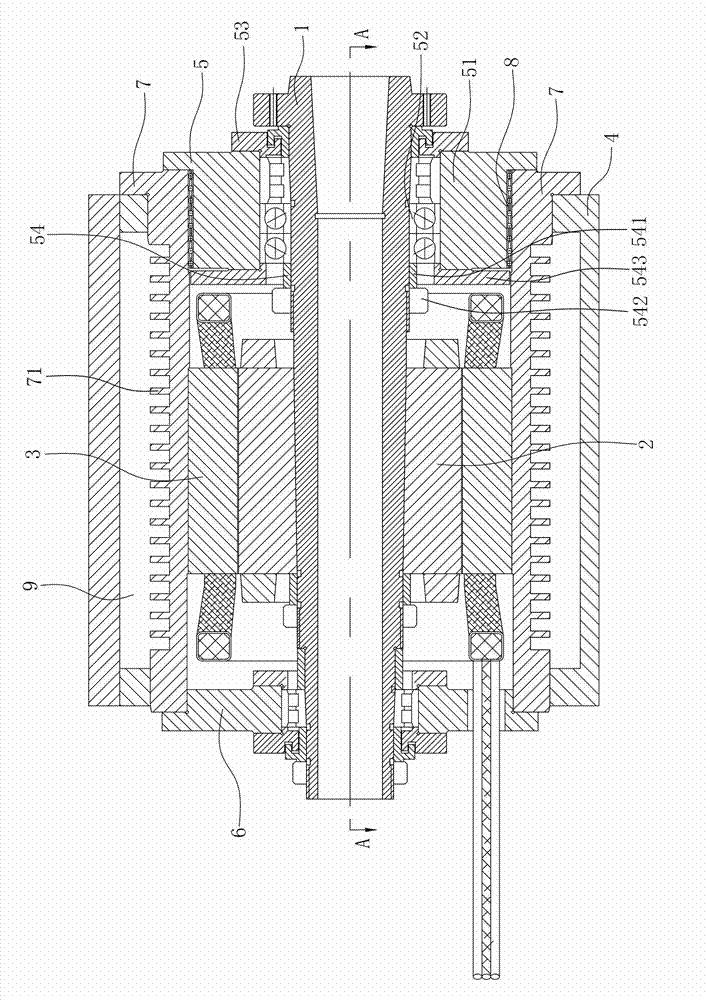
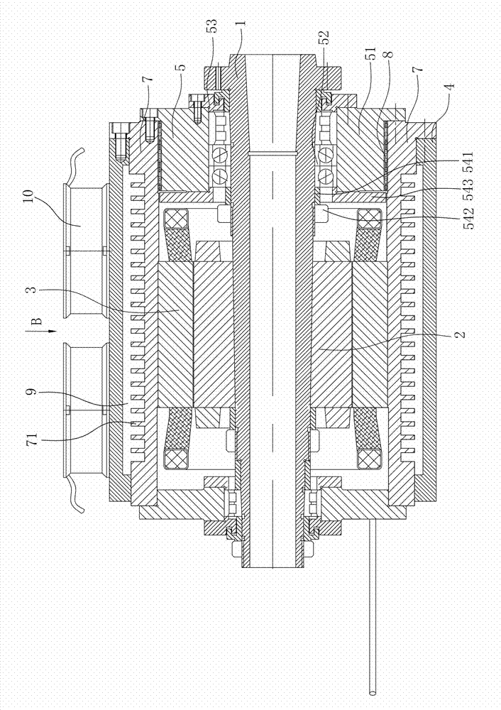
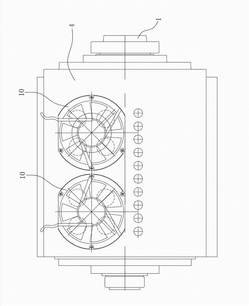
[0017] Figure 1 to Figure 3 It shows an embodiment of a lathe direct-drive electric spindle of the present invention, which includes a main shaft 1, a rotor 2, a stator 3, a case 4, a front bearing assembly 5 and a rear bearing assembly 6, and the main shaft 1 passes through the front bearing assembly 5 and the rear bearing assembly. The bearing assembly 6 is supported on the box body 4, the rotor 2 is installed in the middle of the main shaft 1, the stator 3 is sleeved outside the rotor 2, the box body 4 is equipped with a heat dissipation sleeve 7, the stator 3 is fixed in the heat dissipation sleeve 7, and the front The bearing assembly 5 is set on the front end of the heat dissipation sleeve 7 through the linear bearing 8, which is beneficial to insert the motor rotor shaft parts into the box body 4 from the front end to the rear, which is convenient for assembly; when the bearing is repaired and replaced, the rotor shaft parts can be easily It is taken out as a whole, an...


PUM


Abstract

The invention disclose a direct-drive motorized spindle of a lathe, and the direct-drive motorized spindle comprises a spindle, a rotor, a stator, a box body, a front bearing component and a rear bearing component, wherein the spindle is supported on the box body through the front bearing component and the rear bearing component, the rotor is assembled at the middle part of the spindle, the stator is hollow-sheathed outside the rotor, a heat radiation sleeve is assembled in the box body, the stator is fixed in the heat radiation sleeve, and the front bearing component is sheathed at the frontend of the heat radiation sleeve through a linear bearing. The direct-drive motorized spindle of the lathe has the advantages of being simple and compact in structure, being convenient to assemble, being convenient to maintain and being easy to ensure precision of repeated assembly.

Description

technical field [0001] The invention relates to a lathe spindle structure, in particular to a lathe direct drive electric spindle. Background technique [0002] Most of the existing lathe spindles adopt a belt drive structure, which takes up a lot of space and has a complex structure. When rotating at high speed, it vibrates greatly, generates high noise, and affects machining accuracy. A small number of lathe spindles adopt the electric spindle structure. On the one hand, the existing lathe electric spindles are difficult to reduce the radial size of the sleeve and cannot be directly placed in the lathe head box. On the other hand, they need to be equipped with special refrigeration systems and oil tanks (or water tanks). It takes up a lot of space; most importantly, it is inconvenient to replace bearings and maintain. Once repaired and reassembled, the original positioning reference will be lost, the coaxiality cannot be guaranteed, and the product repair accuracy is diffi...

Claims


Application Information

Patent Timeline
Patent Type & Authority Patents(China)
IPC IPC(8): B23B19/02B23Q11/12
Inventor 熊万里刘岸吕浪吕冰海
Owner 昆山森力玛电机有限公司
Learn More