Isolated insulation cover and isolating switch device

A technology of isolating switch and insulating cover, which is applied in the direction of switchgear, setting of switchgear, electric switch, etc., can solve the problems of large insulation distance, large occupied body, large volume of metal box, etc., and achieve volume reduction, cost saving, The effect of easy installation

Active Publication Date: 2012-04-18
BEIJING QINGCHANG POWER TECH CO LTD
View PDF4 Cites 21 Cited by
  • Summary
  • Abstract
  • Description
  • Claims
  • Application Information

AI Technical Summary

Problems solved by technology

[0002] At present, a large number of power distribution devices mainly insulated by SF6 gas are used in the existing manufacturing technology of power transmission and distribution devices. Various electrical components in the metal box are exposed to SF6 gas, and the internal isolation switch unit and transmission device , The cable outlet device and the connection of the busbar are all exposed in the SF6 gas. The existing isolating switch unit adopts the knife switch type, which occupies a large body, and the SF6 gas in the box cannot leak, and at the same time isolates the grounding switch unit from other electrical appliances. The gas insulation distance between components should be large, which makes the metal box bulky, requires high sealing performance, and complex processing technology, resulting in high cost of the metal box and complicated maintenance and testing.

Method used


Image

  • Isolated insulation cover and isolating switch device
  • Isolated insulation cover and isolating switch device
  • Isolated insulation cover and isolating switch device

Examples


Embodiment Construction

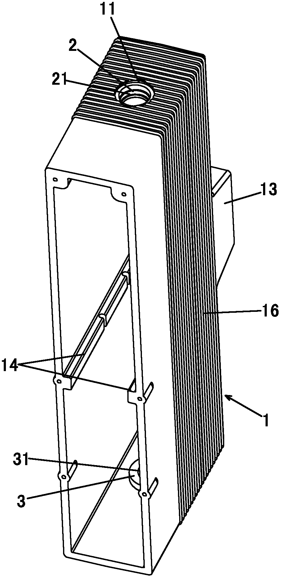
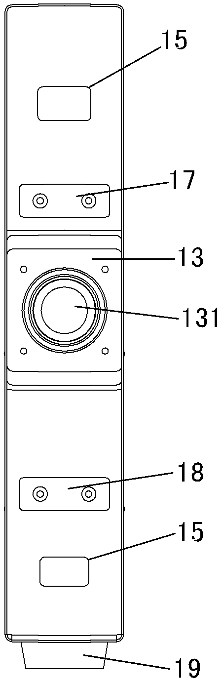
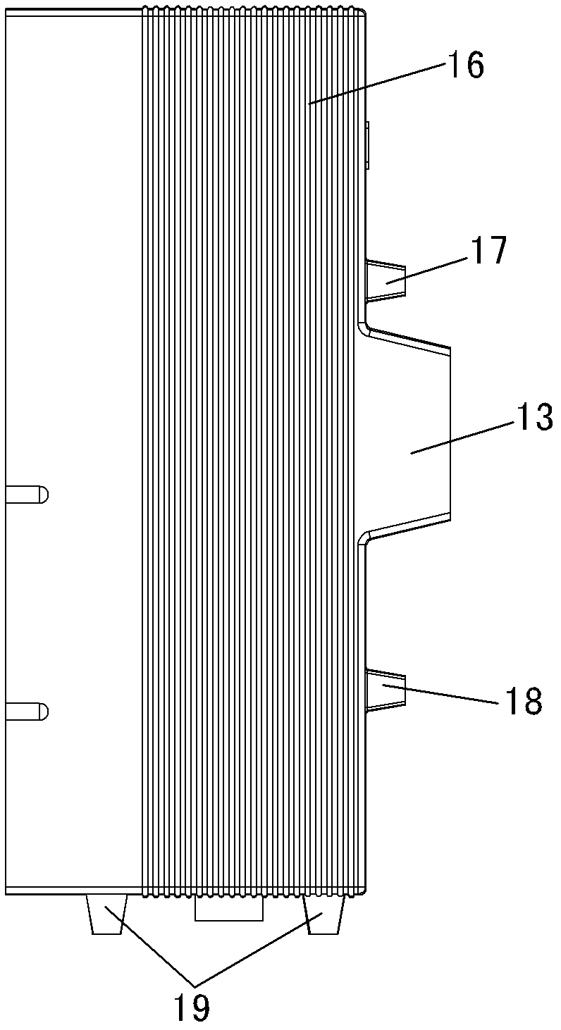
[0023] see Figure 1 to Figure 4 and Figure 7 As shown, the isolation and insulation cover of the present invention includes a cuboid cover body 1 with an open rear made of solid insulating material epoxy resin, and a rear plate can also be installed at the rear open position of the cover body 1 as required. Generally, the situation where the back plate is installed is mostly a place with a harsh environment, and the addition of the back plate can prevent the oxidation of each part of the switch isolation unit in the inner cavity of the cover body 1 . Here we only introduce the usage without a rear panel in a normal environment. The upper plate of the cover body 1 is processed with a tapered upper and lower two-section first stepped hole 11, and a first insulating sleeve 2 is installed in the upper cavity of the first stepped hole 11, and a second insulating sleeve 2 is processed on the first insulating sleeve 2. Stepped hole 21, the lower plate of the cover body 1 is proce...


PUM


Abstract

The invention discloses an isolated insulation cover and an isolating switch device, belonging to the field of conductive connection devices. The isolating switch device is composed of an isolated insulation cover and an insulation switch unit, wherein the insulation cover comprises a cover body which is made of a solid insulation material and has an open back face; an upper plate of the cover body is provided with a first step hole; a first insulation cover is installed in an upper section hole of the first step hole; the first insulation cover is provided with a second step hole; a lower plate of the cover body is provided with a first through hole; a second insulation cover is installed on the first through hole; a third step hole is formed at the center of the second insulation cover; a bump is arranged at the middle part of the front surface of a front plate of the cover body; the bump is provided with a casing connection hole communicated to the inner cavity of the cover body; the left and the right sidewalls of the inner cavity of the cover body are symmetrically provided with a pair of ribs; and a three-position isolating switch unit is installed in the isolated insulation cover. The isolated insulation cover and the isolating switch device disclosed by the invention have the advantages of small size, convenience for installing in on-site construction, reduced size for the box body of the power distribution unit, and saved cost; and the isolating switch device can achieve the functions of three stations consisting of switch-on operation, isolating and earthing.

Description

technical field [0001] The invention relates to the technical field of conductive connection devices, in particular to an isolation insulating cover and an isolation switch device. Background technique [0002] At present, a large number of power distribution devices mainly insulated by SF6 gas are used in the existing manufacturing technology of power transmission and distribution devices. Various electrical components in the metal box are exposed to SF6 gas, and the internal isolation switch unit and transmission device , The cable outlet device and the connection of the busbar are all exposed in the SF6 gas. The existing isolating switch unit adopts the knife switch type, which occupies a large body, and the SF6 gas in the box cannot leak, and at the same time isolates the grounding switch unit from other electrical appliances. The gas insulation distance between the components is large, which makes the metal box bulky, requires high sealing performance, and complex proce...

Claims


Application Information

Patent Timeline
Patent Type & Authority Applications(China)
IPC IPC(8): H02B13/045H01H31/00
Inventor 额尔敦宝力高张焕粉曹寒滨
Owner BEIJING QINGCHANG POWER TECH CO LTD
Why Eureka
Try Eureka