Voltage conversion circuit for forward design of auxiliary winding in flyback topology

A technology of voltage conversion circuit and auxiliary winding, which is applied in the direction of adjusting electric variable, output power conversion device, converting DC power input to DC power output, etc. Problems such as more stable control signals

Inactive Publication Date: 2012-04-18
TECH-POWER ELECTRONICS (SHENZHEN) CO LTD
View PDF4 Cites 1 Cited by
  • Summary
  • Abstract
  • Description
  • Claims
  • Application Information

AI Technical Summary

Problems solved by technology

[0006] The method of flyback topology is adopted between the primary winding N10 and the secondary winding N20 of this voltage conversion circuit, and between the primary winding N10 and the auxiliary winding N30. The advantage of this is that the connection between the auxiliary winding N30 and the secondary winding N20 Due to the relationship between the same phase, the voltage value of the two is proportional to the number of turns. When the output voltage is too low, the voltage of the auxiliary winding N30 is also reduced, so that the control circuit voltage is insufficient and it is in a protection state. However, with the development of the power supply industry There are more and more requirements, and some power supplies that require wide voltage output are produced, such as battery chargers, which require 0-30V or even higher voltages to work normally. If the reverse of the auxiliary winding N30 and the secondary winding N20 is still used If the excitation design is used, the voltage of the control circuit will change due to the change of the output voltage, and a more stable control signal cannot be provided, so providing a stable control voltage has become a necessary pursuit goal.
Example: Assume that when the output voltage V of the secondary winding N20 N20 When it is 30V, since the secondary winding N20 and the auxiliary winding N30 have the same phase, and the pulse generator U100 generally requires a voltage range of 10-20V, set the voltage V output from the auxiliary winding N30 to the pulse generator U100 N30 is 20V (the highest voltage required), the relationship between the voltage turns ratio at this time is V N20 / V N30 = (the number of turns of the secondary winding N20) / (the number of turns of the secondary winding N30)=3 / 2, when the turns ratio is determined, if the output voltage V N20 is relatively small, such as 6V, it can be drawn that V N30 =4V, it cannot meet the requirement that the voltage range required by the pulse generator U100 is 10-20V
It can be seen from the above that when the output voltage range of this voltage conversion circuit is too wide, the pulse generator U100 may not work, resulting in instability of the output voltage

Method used


Image

  • Voltage conversion circuit for forward design of auxiliary winding in flyback topology
  • Voltage conversion circuit for forward design of auxiliary winding in flyback topology
  • Voltage conversion circuit for forward design of auxiliary winding in flyback topology

Examples


Embodiment Construction

[0020] In the following, the voltage conversion circuit of the auxiliary winding forward design in the flyback topology of the present invention will be further described in conjunction with the accompanying drawings and specific implementation methods, so as to understand the technical idea claimed by the present invention more clearly.

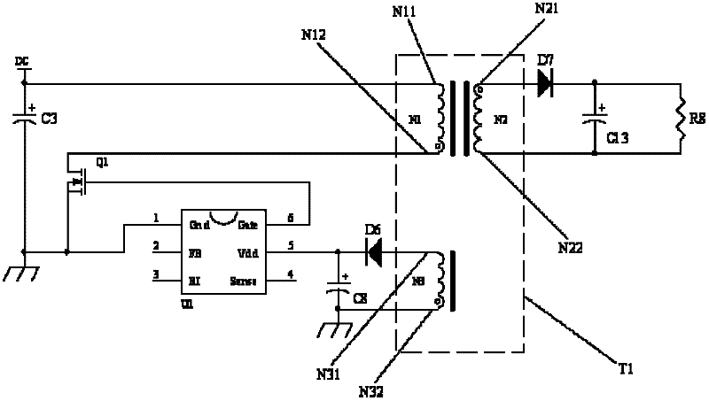
[0021] Such as figure 2 As shown, the voltage conversion circuit of the auxiliary winding forward design in the flyback topology includes the voltage input terminal DC, the transformer T1, the switch tube Q1, the pulse generator U1, the first diode D6, the second diode D7, the load R8, first capacitor C13, second capacitor C8, transformer T1 includes primary winding N1, auxiliary winding N3 and secondary winding N2, primary winding N1 includes first end N11 and second end N12, auxiliary winding N3 includes third end N31 and the fourth terminal N32, the secondary winding N2 includes a fifth terminal N21 and a sixth terminal N22, the voltage ...


PUM


Abstract

The invention discloses a voltage conversion circuit for the forward design of an auxiliary winding in flyback topology. The voltage conversion circuit comprises a transformer, a switching tube, a pulse generator, a first diode, a second diode and a load. The transformer comprises a primary winding, the auxiliary winding and a secondary winding. A voltage input end is connected with the first end of the primary winding of which the second end is connected to the drain of the switching tube. The gate of the switching tube is connected with the pulse generator. The third end of the auxiliary winding is connected with the anode of the first diode of which the cathode is connected to the pulse generator. The fifth end of the secondary winding is connected to the anode of the second diode. The load is connected between the cathode of the second diode and the sixth end of the secondary winding. The second end, a fourth end and the fifth end are corresponding ends. The output voltage of the auxiliary winding is only related to the input voltage of the primary winding, and is not influenced by the output voltage of the secondary winding, so that the pulse generator can be ensured to work stably all the time when the range of the output voltage of the secondary winding is excessively wide.

Description

[0001] technical field [0002] The invention relates to a voltage conversion circuit, in particular to a voltage conversion circuit with a forward design of an auxiliary winding in a flyback topology. Background technique [0003] At present, the commonly used voltage conversion circuit is usually equipped with a pulse width modulation (PWM) controller. The PWM controller compares the output voltage of the voltage conversion circuit through the feedback loop with the reference voltage through the internal comparator, and generates The pulse width of the modulated pulse makes the reference signal actually control the output voltage, so that the voltage conversion circuit can realize stable voltage output and supply power to the load. [0004] There are two power supply methods for the PWM controller in the existing voltage conversion circuit: one is to supply power to it with an external power supply. The miniaturization and weight reduction of circuits also increase unnece...

Claims


Application Information

Patent Timeline
Patent Type & Authority Applications(China)
IPC IPC(8): H02M3/335
Inventor 魏家仁范继光陈胜兵
Owner TECH-POWER ELECTRONICS (SHENZHEN) CO LTD
Why Eureka
Try Eureka