Lc oscillator

A technology of oscillators and capacitors, applied in power oscillators, automatic power control, electric discontinuous tuning, etc., can solve the problems of digital control linearity without oscillators, inability to achieve, and small unit capacitor size.

Inactive Publication Date: 2012-04-18
CAMBRIDGE SILICON RADIO
View PDF0 Cites 2 Cited by
  • Summary
  • Abstract
  • Description
  • Claims
  • Application Information

AI Technical Summary

Problems solved by technology

The problem with this implementation is that the linearity of the varactor diode
The problem with this approach is that the size of the unit capacitor becomes so small that it is practically impossible to achieve
However, the problem with this approach is that the total capacitance seen through the inductor is not a linear function of the number of capacitors switched into the capacitor bank, but rather the following capacitance:
[0010] Subcontainers therefore do not provide the linearity required for digital control of oscillators

Method used


Image

  • Lc oscillator
  • Lc oscillator
  • Lc oscillator

Examples


Embodiment Construction

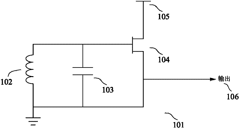
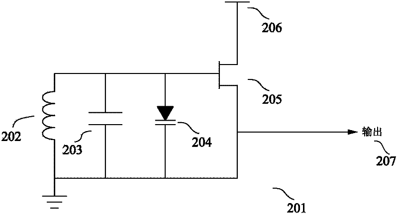
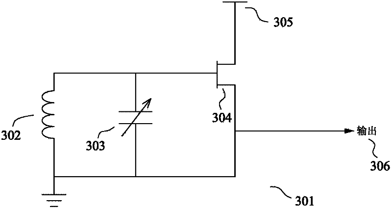
[0025] An oscillator capable of generating signals having different frequencies within a predetermined frequency range may include capacitive elements and inductive elements. The capacitive element may include more than two capacitor arrays. Each array may include one or more capacitors switchably connected in parallel with the inductive element to control the frequency of the output signal. One of the capacitive arrays may be connected to only a part of the inductive element so that it sees a smaller inductance than the other array. Since the effect of a particular capacitance on the output frequency depends on the inductance it is connected to, connecting the array to only a portion of the inductance can be used to increase the size of the capacitance required to achieve a particular frequency step. This is because a capacitor connected to only a portion of the inductance produces less frequency variation in the output signal than if the capacitor had been connected to the ...


PUM


Abstract

An oscillator comprising a capacitive element and an inductive element for generating an output signal having a predetermined frequency, the capacitive element comprising two or more capacitive arrays, each array having one or more capacitors that are switchably connectable in parallel with the inductive element so as to control the frequency of the output signal, and at least one of those arrays being connected to only part of the inductive element such that, when a capacitor in said one array is connected to that part, the resulting change in the frequency of the output signal is smaller than it would have been if the capacitor had been connected to the whole of the inductive element.

Description

technical field [0001] The present invention relates to LC oscillators, and more particularly to LC oscillators comprising a set of switchable capacitors for adjusting the output frequency of the oscillator. Background technique [0002] A phase-locked loop (PLL) is known as a circuit for generating a signal having a predetermined frequency relationship to a reference signal. In its most basic configuration, a phase-locked loop consists of an oscillator controlled by a feedback loop. The feedback loop takes the output of the oscillator, compares it to a reference signal, and adjusts the oscillator accordingly. The feedback loop usually includes: a frequency divider (divider), which is used to divide the output signal; a phase comparator, which is used to compare the phase of the frequency-divided signal with a reference signal; and a charge pump, which is used to output according to the phase comparison result. Speed ​​up or slow down the oscillator's charge pulse. PLLs a...

Claims


Application Information

Patent Timeline
Patent Type & Authority Applications(China)
IPC IPC(8): H03L7/099A47C1/034
CPCH03B5/1243H03B5/1228H03B5/1203H03B5/1265H03B1/00H03B5/1212H03B5/12H03J5/246H03L7/0991
Inventor 尼古拉斯·索尔宁
Owner CAMBRIDGE SILICON RADIO
Why Eureka
Try Eureka