Steel stranded rubber support and production method thereof
A technology of rubber bearings and steel hinges, which is applied to bridge parts, bridges, buildings, etc., can solve the problems of inconvenient installation and maintenance, high maintenance frequency, and short service life, and achieve cost-free maintenance, flexible rotation, and long service life. Effect
- Summary
- Abstract
- Description
- Claims
- Application Information
AI Technical Summary
Problems solved by technology
Method used
Image
Examples
Embodiment 1
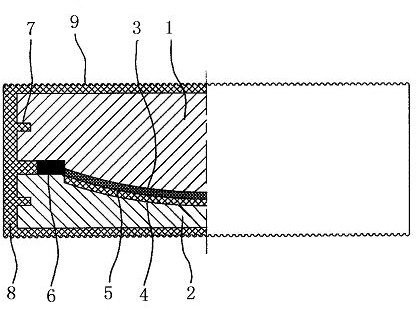
[0040] The first step, preparation of convex spherical crown steel hinge support body and concave spherical crown steel hinge support body
[0041] A convex spherical surface 3 and a notch 7 are processed on the convex spherical crown steel hinge support body 1, a concave spherical surface 4 and a notch 7 are processed on the concave spherical crown steel hinge support body 2, and the convex spherical surface 3 and the concave spherical surface 4 are respectively set Wear-resistant layers of different materials form a spherical friction pair 5;
[0042] The second step, assembly
[0043] Install the elastic support element 6 on the top surface of the convex spherical crown steel hinge support body 1 or the concave spherical crown steel hinge support body 2 arranged below, and connect the convex spherical surface 3 of the convex spherical crown steel hinge support body 1 with the concave spherical crown steel hinge The concave spherical surface 4 of the support body 2 ...
Embodiment 2
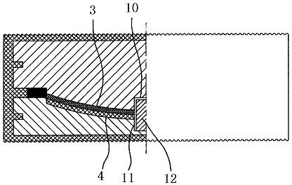
[0045] The first step, preparation of convex spherical crown steel hinge support body and concave spherical crown steel hinge support body
[0046] A convex spherical surface 3, a convex pin hole 10, and a notch 7 are processed on the convex spherical crown steel hinge support body 1, a concave spherical surface 4, a concave surface pin hole 11, and a notch 7 are processed on the concave spherical crown steel hinge support body 2, Wear-resistant layers of different materials are respectively arranged on the convex spherical surface 3 and the concave spherical surface 4 to form a spherical friction pair 5;
[0047] The second step, assembly
[0048] Install the elastic supporting element 6 on the top surface of the convex spherical crown steel hinge support body 1 or the concave spherical crown steel hinge support body 2 arranged below, and install the shear pin 12 in the convex surface pin hole 10 or the concave surface pin hole arranged below In 11, the convex spheri...
Embodiment 3
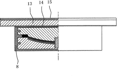
[0050] The first step, preparation of convex spherical crown steel hinge support body and concave spherical crown steel hinge support body
[0051] A convex spherical surface 3, a convex pin hole 10, and a notch 7 are processed on the convex spherical crown steel hinge support body 1, a concave spherical surface 4, a concave surface pin hole 11, and a notch 7 are processed on the concave spherical crown steel hinge support body 2, Wear-resistant layers of different materials are respectively arranged on the convex spherical surface 3 and the concave spherical surface 4 to form a spherical friction pair 5;
[0052] The second step, assembly
[0053] Install the elastic supporting element 6 on the top surface of the convex spherical crown steel hinge support body 1 or the concave spherical crown steel hinge support body 2 arranged below, and install the shear pin 12 in the convex surface pin hole 10 or the concave surface pin hole arranged below In 11, the convex spheri...
PUM
 Abstract
Description
Claims
Application Information
 - R&D
- Intellectual Property
- Life Sciences
- Materials
- Tech Scout
- Unparalleled Data Quality
- Higher Quality Content
- 60% Fewer Hallucinations
Browse by: Latest US Patents, China's latest patents, Technical Efficacy Thesaurus, Application Domain, Technology Topic, Popular Technical Reports.
© 2025 PatSnap. All rights reserved.Legal|Privacy policy|Modern Slavery Act Transparency Statement|Sitemap|About US| Contact US: help@patsnap.com


