Steel stranded rubber support and production method thereof

A rubber bearing and steel hinge technology, applied in bridge parts, bridges, buildings, etc., can solve the problems of inconvenient installation and maintenance, short service life, and high maintenance frequency, and achieve the effects of cost-free maintenance, long service life and flexible rotation.

Active Publication Date: 2013-01-23
HEBEI BAOLI ENG EQUIP GRP CO LTD
View PDF8 Cites 0 Cited by
  • Summary
  • Abstract
  • Description
  • Claims
  • Application Information

AI Technical Summary

Problems solved by technology

Plate bearings are prone to bearing deflection during use, high maintenance frequency, and short service life
The structure of the spherical bearing includes an upper bearing plate, a spherical crown lining plate, a spherical concave lining plate and a lower bearing plate. The sliding and rotating parts of the spherical bearing are not well sealed, and the cost is high, and installation and maintenance are inconvenient.

Method used


Image

  • Steel stranded rubber support and production method thereof
  • Steel stranded rubber support and production method thereof
  • Steel stranded rubber support and production method thereof

Examples


Embodiment 1

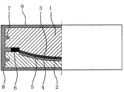
[0040] The first step, preparation of convex spherical crown steel hinge support body and concave spherical crown steel hinge support body

[0041] A convex spherical surface 3 and a notch 7 are processed on the convex spherical crown steel hinge support body 1, a concave spherical surface 4 and a notch 7 are processed on the concave spherical crown steel hinge support body 2, and the convex spherical surface 3 and the concave spherical surface 4 are respectively set Wear-resistant layers of different materials form a spherical friction pair 5;

[0042] The second step, assembly

[0043] Install the elastic support element 6 on the top surface of the convex spherical crown steel hinge support body 1 or the concave spherical crown steel hinge support body 2 arranged below, and connect the convex spherical surface 3 of the convex spherical crown steel hinge support body 1 with the concave spherical crown steel hinge The concave spherical surface 4 of the support body 2 is in co...

Embodiment 2

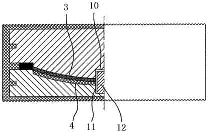
[0045] The first step, preparation of convex spherical crown steel hinge support body and concave spherical crown steel hinge support body

[0046] A convex spherical surface 3, a convex pin hole 10, and a notch 7 are processed on the convex spherical crown steel hinge support body 1, a concave spherical surface 4, a concave surface pin hole 11, and a notch 7 are processed on the concave spherical crown steel hinge support body 2, Wear-resistant layers of different materials are respectively arranged on the convex spherical surface 3 and the concave spherical surface 4 to form a spherical friction pair 5;

[0047] The second step, assembly

[0048] Install the elastic supporting element 6 on the top surface of the convex spherical crown steel hinge support body 1 or the concave spherical crown steel hinge support body 2 arranged below, and install the shear pin 12 in the convex surface pin hole 10 or the concave surface pin hole arranged below In 11, the convex spherical surf...

Embodiment 3

[0050] The first step, preparation of convex spherical crown steel hinge support body and concave spherical crown steel hinge support body

[0051] A convex spherical surface 3, a convex pin hole 10, and a notch 7 are processed on the convex spherical crown steel hinge support body 1, a concave spherical surface 4, a concave surface pin hole 11, and a notch 7 are processed on the concave spherical crown steel hinge support body 2, Wear-resistant layers of different materials are respectively arranged on the convex spherical surface 3 and the concave spherical surface 4 to form a spherical friction pair 5;

[0052] The second step, assembly

[0053] Install the elastic supporting element 6 on the top surface of the convex spherical crown steel hinge support body 1 or the concave spherical crown steel hinge support body 2 arranged below, and install the shear pin 12 in the convex surface pin hole 10 or the concave surface pin hole arranged below In 11, the convex spherical surf...


PUM


Abstract

The invention belongs to the technical field of bridge supports, and discloses a steel stranded rubber support and a production method thereof. The steel stranded rubber support is mainly technically characterized by comprising a convex spherical crown steel stranded support with a convex spherical surface and a concave spherical crown steel stranded support with a concave spherical surface, wherein the convex spherical crown steel stranded support and the concave spherical crown steel stranded support are coated or partly coated by an elastomer. The steel stranded rubber support provided by the invention is large in corner so as to be capable of self-adapting to a corner of a girder body and to effectively prevent biasing of plate type rubber supports. And the convex spherical crown steel stranded support and the concave spherical crown steel stranded support are coated or partly coated by the elastomer, therefore, the stress is not further applied to the peripheral rubber of the support and other elastomer protection layers, and good sealing performance and long service life are achieved. The steel stranded rubber support has the advantages of plate type supports and global supports, also has the advantages of convenience for installation and low cost, and is free of maintenance.

Description

technical field [0001] The invention belongs to the technical field of bridge supports, in particular to a steel hinge rubber support and a preparation method thereof. Background technique [0002] The bearings used in bridge engineering construction include plate bearings, spherical bearings, pot bearings, etc. The structure of the plate bearings includes rubber cushions with stiffened steel plates, and multiple layers of rubber cushions are stacked as needed during installation. . Plate bearings are prone to bearing deflection during use, high maintenance frequency, and short service life. The structure of the spherical support includes an upper support plate, a spherical crown liner, a spherical concave liner and a lower support plate. The sliding and rotating parts of the spherical support have poor sealing performance, high cost, and inconvenient installation and maintenance. Contents of the invention [0003] The first technical problem to be solved by the present ...

Claims


Application Information

Patent Timeline
Patent Type & Authority Patents(China)
IPC IPC(8): E01D19/04
Inventor 陈广进
Owner HEBEI BAOLI ENG EQUIP GRP CO LTD
Why Eureka
Try Eureka