Forced ventilation system of engine crankcase

A technology of forced ventilation and crankcase, which is applied in crankcase ventilation, engine components, machines/engines, etc. It can solve the problems of no oil-gas separation ability and increase engine oil consumption rate, etc., and achieve improved scavenging effect and oil-gas separation efficiency , Prevent the oil from deteriorating and corroding the machine parts

Inactive Publication Date: 2012-04-25
CHONGQING CHANGAN AUTOMOBILE CO LTD
View PDF5 Cites 1 Cited by
  • Summary
  • Abstract
  • Description
  • Claims
  • Application Information

AI Technical Summary

Problems solved by technology

Because the needle PCV valve has the function of oil-gas separation, which improves the oil-gas separation efficiency of the PCV valve passage, while the breather pipe only serves as a pipeline connection and has no oil-gas separation capability, so part of the oil brought into the oil-gas separation chamber of the breather pipe enters the inlet In the air system, the oil consumption rate of the engine is increased

Method used


Image

  • Forced ventilation system of engine crankcase
  • Forced ventilation system of engine crankcase
  • Forced ventilation system of engine crankcase

Examples


Embodiment Construction

[0020] The present invention will be further described below in conjunction with the accompanying drawings.

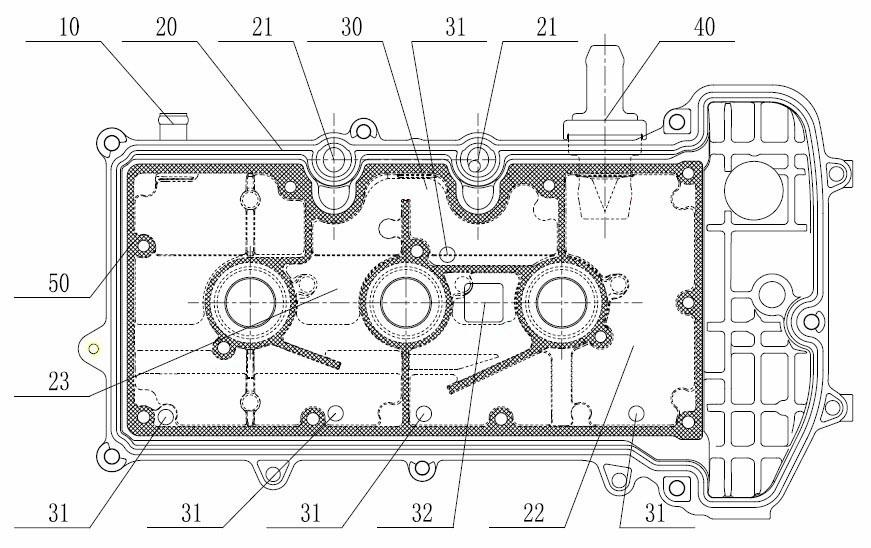
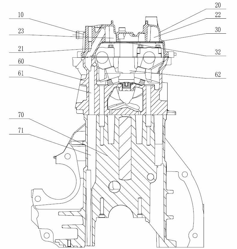
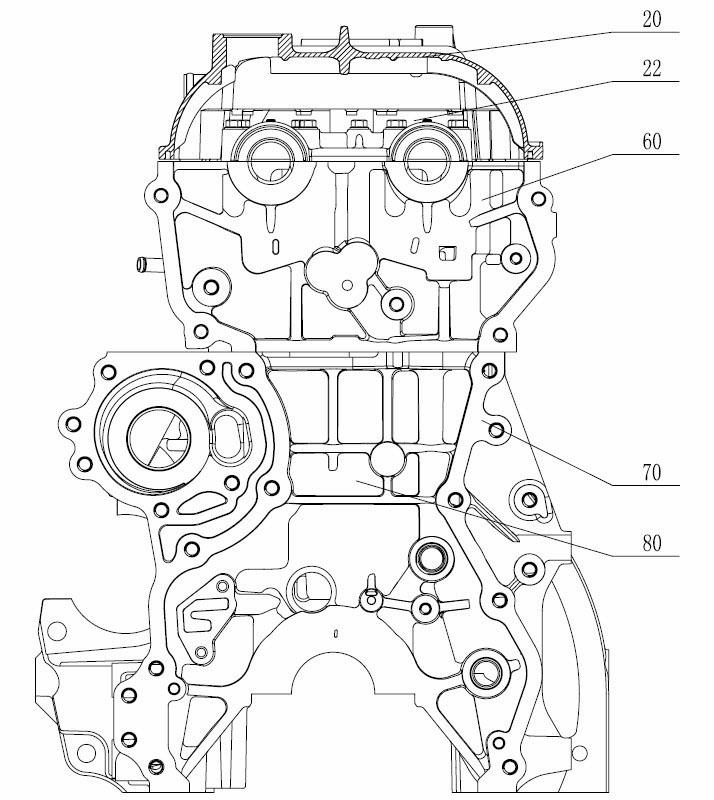
[0021] see figure 1 and figure 2 The shown forced ventilation system for a crankcase of an engine includes a PCV valve oil-gas separation chamber 22 and a breather pipe oil-air separation chamber 23 formed by a vent cover plate 30 and a cylinder head cover 20 connected thereon, and is arranged on the cylinder head cover. And the needle type PCV valve 40 communicated with the oil-gas separation chamber 22 of the PCV valve, the breather pipe 10 which is arranged on the cylinder head cover and communicates with the oil-gas separation chamber 23 of the breather pipe, the oil-gas separation chamber 22 of the PCV valve communicates with the intake manifold through the pipeline Connected, the vent pipe oil-gas separation chamber 23 is connected with the air filter through a pipeline; in order to improve the oil-gas separation efficiency of the vent pipe passage, the volume ...


PUM


Abstract

The invention discloses a forced ventilation system of an engine crankcase, wherein the forced ventilation system comprises a PCV (pollution control valve) oil gas separation chamber, a ventilation pipe oil gas separation chamber, a needle-type PCV and a ventilation pipe, wherein the PCV oil gas separation chamber is composed of a ventilation cover plate and an air cylinder cover; the needle-type PCV is communicated with the PCV oil gas separation chamber; and the ventilation pipe is communicated with the ventilation pipe oil gas separation chamber. The forced ventilation system is characterized in that the volume of the ventilation pipe oil gas separation chamber is greater than that of the PCV oil gas separation chamber; one end of each of two first blow-by channels arranged on the air cylinder cover is positioned in the ventilation pipe oil gas separation chamber, and the other end of each of the two first blow-by channel arranged on the air cylinder cover is corresponding to a second blow-by channel on the air cylinder cover; the second blow-by channel is corresponding to a third blow-by channel on the crankcase; and the bottom of the ventilation pipe oil gas separation chamber is provided with three oil return holes, and the bottom of the PCV oil gas separation chamber is provided with two oil return holes. Because the scavenging effect is improved obviously, the blow-by in the crankcase is timely exhausted into an air intake system so as to prevent accelerated engine oil deterioration and engine element corrosion caused by blowby; and the oil gas separation efficiency of the ventilation pipeline is improved greatly, thus the engine oil consumption of the engine is lowered.

Description

technical field [0001] The invention belongs to automobile engine technology, in particular to an engine crankcase forced ventilation system. Background technique [0002] The engine crankcase forced ventilation system using a needle PCV valve is generally composed of a PCV valve passage and a breather pipe passage. The PCV valve path is composed of a needle PCV valve, a PCV valve oil-air separation chamber and a pipeline connected to the intake manifold. The vent pipe path is composed of the vent pipe, the vent pipe oil-gas separation chamber and the pipeline connected to the air filter. [0003] In order to make the overall arrangement of the engine compact and facilitate pipeline connection, the needle PCV valve and the breather pipe are usually installed on the cylinder head cover, and the PCV valve oil-air separation chamber and the breather pipe oil-air separation chamber are arranged on the cylinder head cover. The two oil-gas separation chambers consist of a cylind...

Claims


Application Information

Patent Timeline
Patent Type & Authority Applications(China)
IPC IPC(8): F01M13/04F02F7/00
Inventor 任志勇何海珠邱阳王茂辉王垣钦
Owner CHONGQING CHANGAN AUTOMOBILE CO LTD
Why Eureka
Try Eureka