Operating mechanism of modularized breaker

An operating mechanism and circuit breaker technology, applied in the protection switch operation/release mechanism, circuit, and components of the protection switch, etc., can solve the problems of the circuit breaker contact not being energized, the thermoplastic fixed connection strength is low, and the pollution removal is difficult. , to achieve the effect of improving product reliability and life, easy large-scale automated production, and fewer parts

Active Publication Date: 2014-11-19
ZHEJIANG CHINT ELECTRIC CO LTD
View PDF9 Cites 2 Cited by
  • Summary
  • Abstract
  • Description
  • Claims
  • Application Information

AI Technical Summary

Problems solved by technology

Since at least two kinds of glues need to be mixed for bonding, and then sent to heating equipment for drying treatment, it not only requires a long period of time for the adhesive to be cured, but also the glue will inevitably flow out during this process, and it is inevitable that frequent sticking occurs. The contact agent pollutes the moving contact of the circuit breaker, which may cause the circuit breaker contact to have a problem of no power, and it takes a lot of man-hours to clean up the pollution
If the hot riveting fixed connection method is used, it will not only lead to a significant drop in production efficiency, but also this kind of hot riveting needs to use more expensive materials as supports, and the strength of the thermoplastic fixed connection is low
Moreover, the method of rigidly and fixedly connecting the moving contact with the contact makes the operating force or tripping force of the operating mechanism too large, which is not conducive to the life of the circuit breaker.

Method used


Image

  • Operating mechanism of modularized breaker
  • Operating mechanism of modularized breaker
  • Operating mechanism of modularized breaker

Examples


Embodiment Construction

[0021] The specific implementation of the operating mechanism of the modularized circuit breaker of the present invention will be further described below in conjunction with the embodiments shown in the accompanying drawings, taking the miniature circuit breaker as an example. The operating mechanism of the modular circuit breaker of the present invention is not limited to the description of the following embodiments.

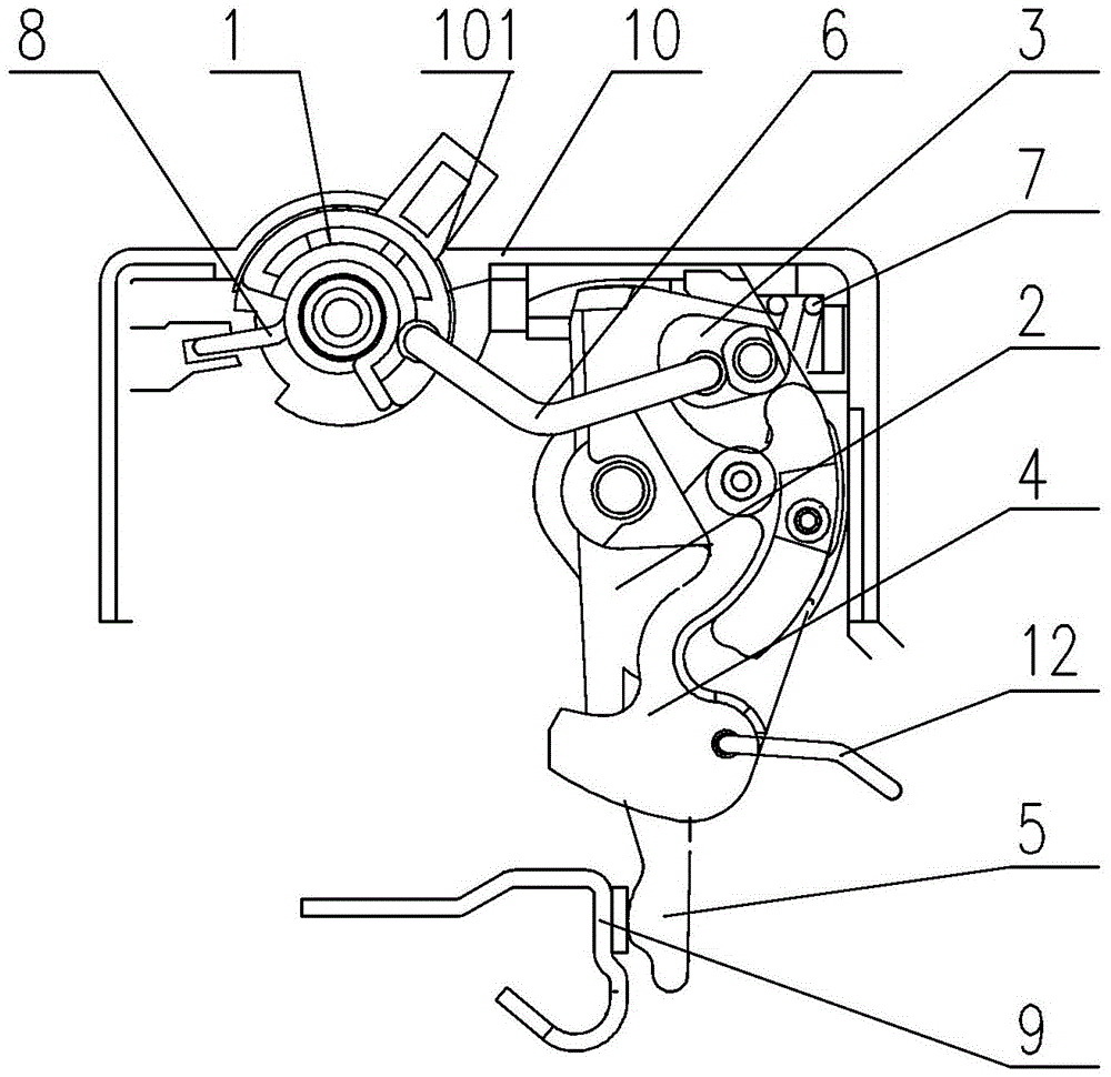
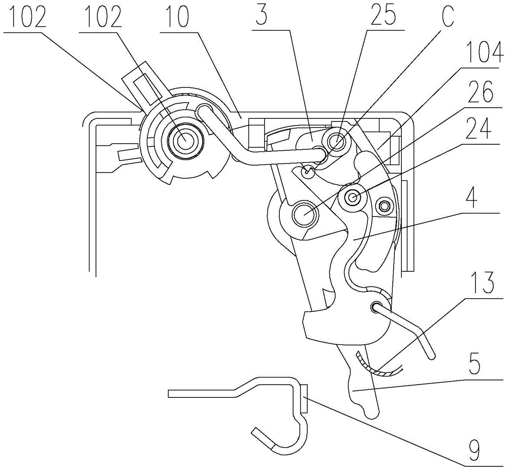
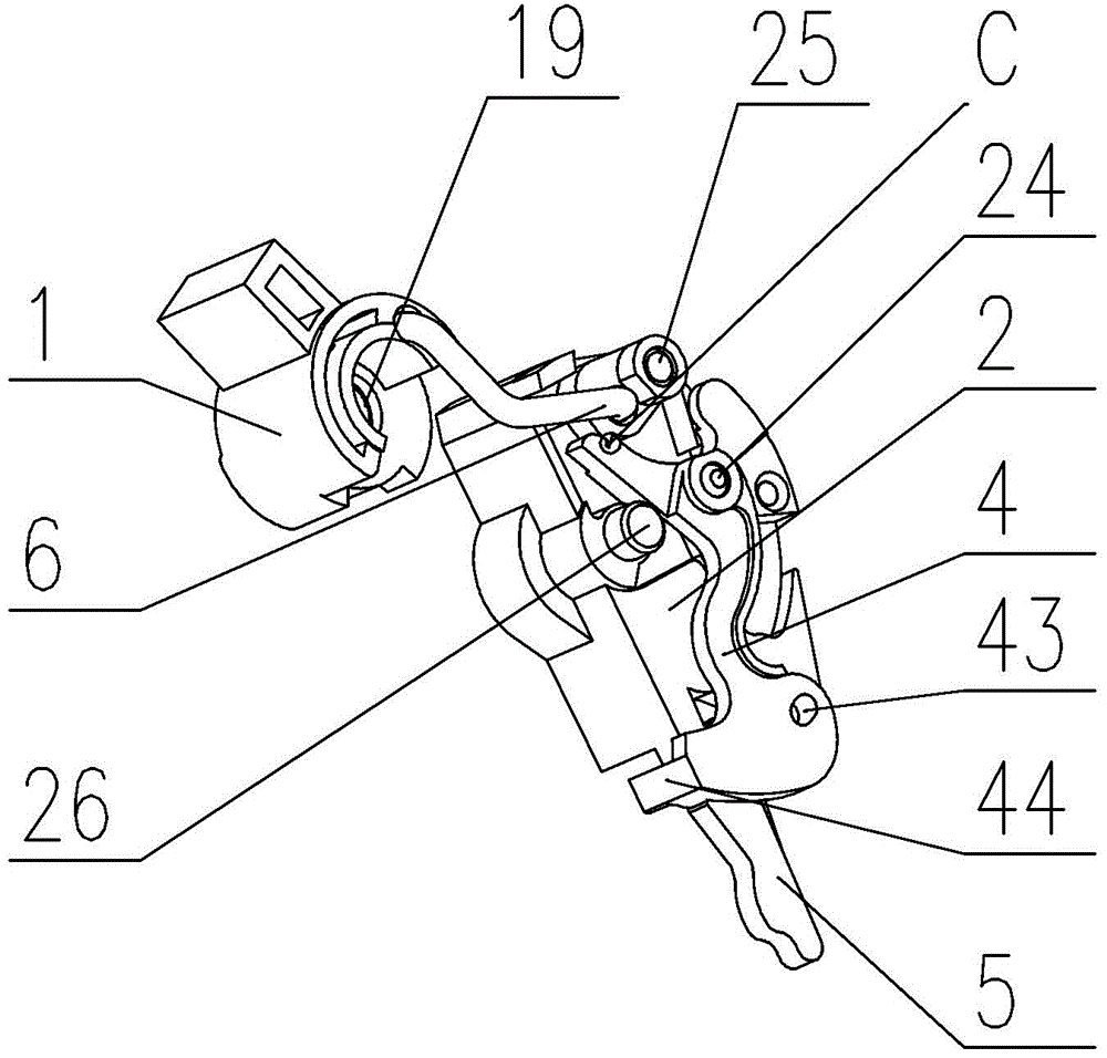
[0022] see Figures 1 to 6 The operating mechanism of the miniature circuit breaker shown includes a circuit breaker case 10, a lever 3, a lock 4, a moving contact 5, an operating handle 1 and a contact support 2 that are pivotally mounted on the circuit breaker case 10, and a fixed installation The static contact 9 on the circuit breaker case 10, the return spring 8 connected to the circuit breaker case 10 and the operating handle 1 respectively, the energy storage spring 7 connected to the circuit breaker case 10 and the contact support 2 respectively, and th...


PUM


Abstract

The invention provides an operating mechanism of a modularized breaker. A lever and a lock catch are respectively pivotedly installed at a contact support; there are two states between a first hasp surface on the lever and a second hasp surface on the lock catch, wherein the two states include a contact locking state and a separating unlocking state; on the condition of the contact locking state, the lever, the lock catch and the contact support can not make relative free motions; and on the condition of the separating unlocking state, the lever and the lock catch can make free rotations relatively to the contact support. A moving contact is pivotedly installed at the contact support through a first connection structure and a pressure spring; one end of the spring is connected with the contact support and the other end of the spring is connected with the moving contact; and the spring is used for energy storage and providing contact pressures for the moving contact and a static contact, wherein the moving contact and the static contact are in a closed state. The lock catch is provided with a restriction member that is installed and connected through a second connection structure; an elastic antenna on the restriction member and a glide plane on the housing are contacted and are in a sliding fit. According to the invention, the operating mechanism has advantages of improved reliability and service life, small volume, few parts, and low cost as well as is easy to be produced automatically in a large scale.

Description

technical field [0001] The invention relates to an operating mechanism of a low-voltage molded case circuit breaker, in particular to an operating mechanism of a modular miniature circuit breaker. Background technique [0002] Modularized miniature circuit breakers are favored by the market due to their small size, high breaking capacity and easy rail-type installation. At present, they are widely used in public buildings and residential buildings for opening, closing, overload and short-circuit protection of electrical appliances. Existing modularized miniature circuit breakers generally adopt the operating mechanism disclosed in the Chinese invention patent application CN88103427A. The moving contact support of the plate on the pivot and a mechanical interlock that can be broken by the action of the trip bar by a stop of the trip bar and a latch rotatably mounted on the mandrel of the plate Cooperatingly constituted, the chain is directly connected to the latch, and this ...

Claims


Application Information

Patent Timeline
Patent Type & Authority Patents(China)
IPC IPC(8): H01H71/10
CPCH01H71/526
Inventor 杨峰祝利杰王先锋司莺歌周长青
Owner ZHEJIANG CHINT ELECTRIC CO LTD
Why Eureka
Try Eureka