
Printed circuit board (PCB) assembly and PCB assembly assembling method

A technology of printed boards and components, applied in the field of electronics, can solve the problems of occupying electrical signal transmission channels, high material costs, and large printed board sizes, and achieve the effects of reducing design complexity, saving material costs, and improving signal quality

Inactive Publication Date: 2013-09-11
HUAWEI MACHINERY
View PDF3 Cites 0 Cited by
  • Summary
  • Abstract
  • Description
  • Claims
  • Application Information

AI Technical Summary

Problems solved by technology

[0008] Due to the large number of components, adopting a one-board integration scheme, that is, a scheme that prints and integrates all components in one piece, will cause many problems: 1. The size of the printed board is large, the processing yield of large-sized printed boards, and the utilization of boards rate, component assembly efficiency, etc. are low
[0009] Although the multi-board series solution solves the problem of oversized printed boards in the one-board integration solution, this solution has at least the following problems: 1. Since two printed boards need to communicate with each other, when three or more printed boards need to communicate with each other, When the printed boards are connected, the components on the first printed board are connected to the components on the third printed board, which needs to occupy the electrical signal transmission channel on the second printed board, increasing the design complexity of the second printed board , high material cost
Therefore, no matter what kind of function combination the product needs to achieve, it needs three printed boards to realize it together, and the function combination is not flexible
3. The high-speed components of the first printed board are connected to the high-speed components of the third printed board, and the signal transmission path includes: the first printed board, the connecting device between the first printed board and the second printed board, For the second printed board, the connecting device between the second printed board and the third printed board, and the third printed board, for high-speed signals, the interface between each two objects will be a signal reflection point, because the signal There are many reflection points on the transmission channel, resulting in poor quality electrical connections between high-speed devices

Method used


Image

  • Printed circuit board (PCB) assembly and PCB assembly assembling method
  • Printed circuit board (PCB) assembly and PCB assembly assembling method
  • Printed circuit board (PCB) assembly and PCB assembly assembling method

Examples


Embodiment Construction

[0025] The following will clearly and completely describe the technical solutions in the embodiments of the present invention with reference to the accompanying drawings in the embodiments of the present invention. Obviously, the described embodiments are only some, not all, embodiments of the present invention. Based on the embodiments of the present invention, all other embodiments obtained by persons of ordinary skill in the art without creative efforts fall within the protection scope of the present invention.

[0026] An embodiment of the present invention provides a printed board assembly, such as figure 2 as shown, figure 2 The rectangle with small dots in the center is the electronic component 201, the black rectangle is the pin 202 of the electronic component, the rectangle with diagonal lines in the left direction is the common printed board 206, the rectangle with diagonal lines in the right direction is the radio frequency printed board 207, and the blank rectang...


PUM


Abstract

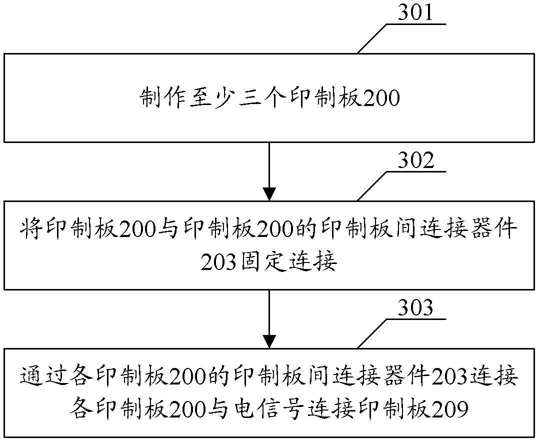
An embodiment of the invention discloses a printed circuit board (PCB) assembly and a PCB assembly assembling method. The PCB assembly comprises at least three PCBs 200. The each PCB 200 has an electronic component 201. And the each electronic component 201 is connected with a connecting device between the PCBs 203 of the PCB 200 where the electronic component 201 is located through an electric signal transmission channel 204 in the PCB 200. The PCB 200 is fixedly connected with the connecting device between the PCBs 203 of the PCB 200. The each PCB 200 is connected with an electric signal connection PCB 209 through the connecting device between the PCBs 203 of the each PCB 200. At least three PCBs realize connection through the connecting device between the PCBs so as to form a bus connection structure. The each PCB is independent. Design complexity can be reduced and reflection points can be reduced too. Therefore, function configuration of the PCB assembly is flexible. Material costs can be saved and signal quality can be increased.

Description

technical field [0001] The invention relates to the field of electronic technology, in particular to a printed board assembly and a method for assembling the printed board assembly. Background technique [0002] With the development of electronic technology, the circuit scale tends to increase exponentially, and the circuit often uses a printed circuit board (PCB) as its carrier. The embodiment of the present invention will take the application of PCB in an active antenna system (Adaptive Antenna system, AAS) as an example for illustration. It can be understood that the application of PCB is not limited to AAS, so this example is not an exhaustive list of PCB application fields. . [0003] AAS is an antenna system that uses an antenna array and can adaptively adjust the weighted value according to the spatial characteristics of the signal to adjust its direction circle to form multiple adaptive beams to suppress interference and extract signals. [0004] With the applicati...

Claims


Application Information

Patent Timeline
Patent Type & Authority Patents(China)
IPC IPC(8): H05K1/18H01R12/70H05K3/36
Inventor 潘友兵杨瑞泉李洪彩林强
Owner HUAWEI MACHINERY
Learn More