Spot welder electrode part

A technology of electrode part and spot welding machine, applied in the direction of cooling electrodes, electrode features, pressure electrodes, etc., can solve problems such as poor power supply, overheating of small contacts 195, insufficient cooling of protrusions 191a, etc., and achieve the effect of preventing overheating

Inactive Publication Date: 2012-04-25
SHINKOKIKI CO LTD +1
View PDF1 Cites 2 Cited by
  • Summary
  • Abstract
  • Description
  • Claims
  • Application Information

AI Technical Summary

Problems solved by technology

In addition, since it is necessary to avoid interference, it is not possible to increase the thickness dimension where the small contact 195 is joined to the protruding portion 191a. As a result, since the thickness dimension of the protruding portion 191a cannot be increased, the cooling water flow path cannot be formed in the protruding portion 191a.
[0006] like Image 6 As shown, on the electrode holder 191, the cooling water passage 191c is formed to the vicinity of the base of the protruding portion 191a. However, since the cooling water passage 191c is not formed on the protruding portion 191a, insufficient cooling of the protruding portion 191a and the protruding portion during welding may occur. 191a is softened and bent due to heat, and the welding accuracy cannot be ensured
In addition, the mounting portion 195a and the mounting hole 191b are oxidized due to heat, and there are also problems of poor electrical conduction between the electrode holder 191 and the small contact 195 and poor welding.
In addition, since the protruding portion 191a is not sufficiently cooled, it is difficult to transfer heat from the small contact 195 to the protruding portion 191a, and the small contact 195 may be overheated.
Therefore, the small contacts 195 are softened and deformed, and there is a problem that the small contacts 195 must be replaced frequently in order to ensure the welding quality.

Method used


Image

  • Spot welder electrode part
  • Spot welder electrode part
  • Spot welder electrode part

Examples


no. 1 approach

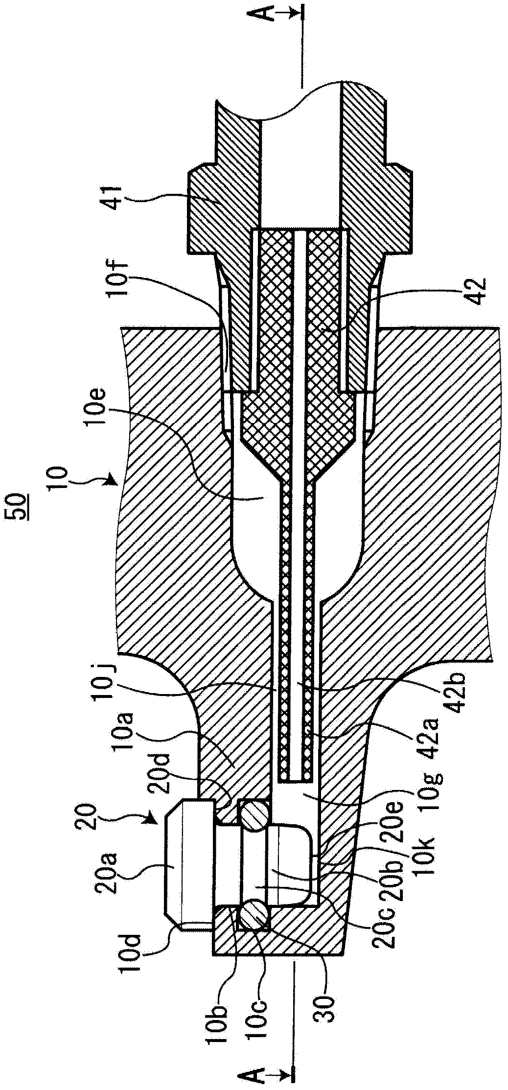
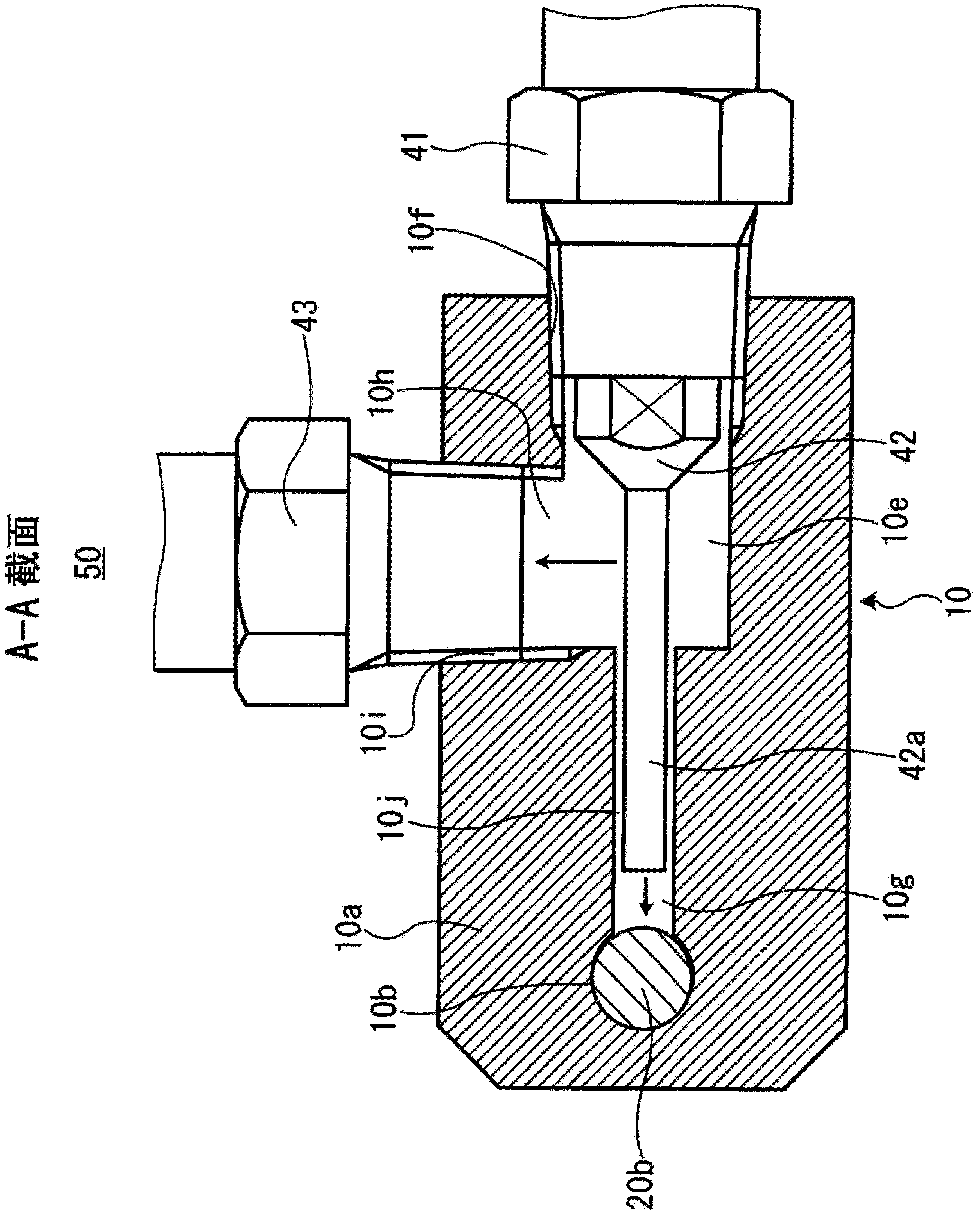
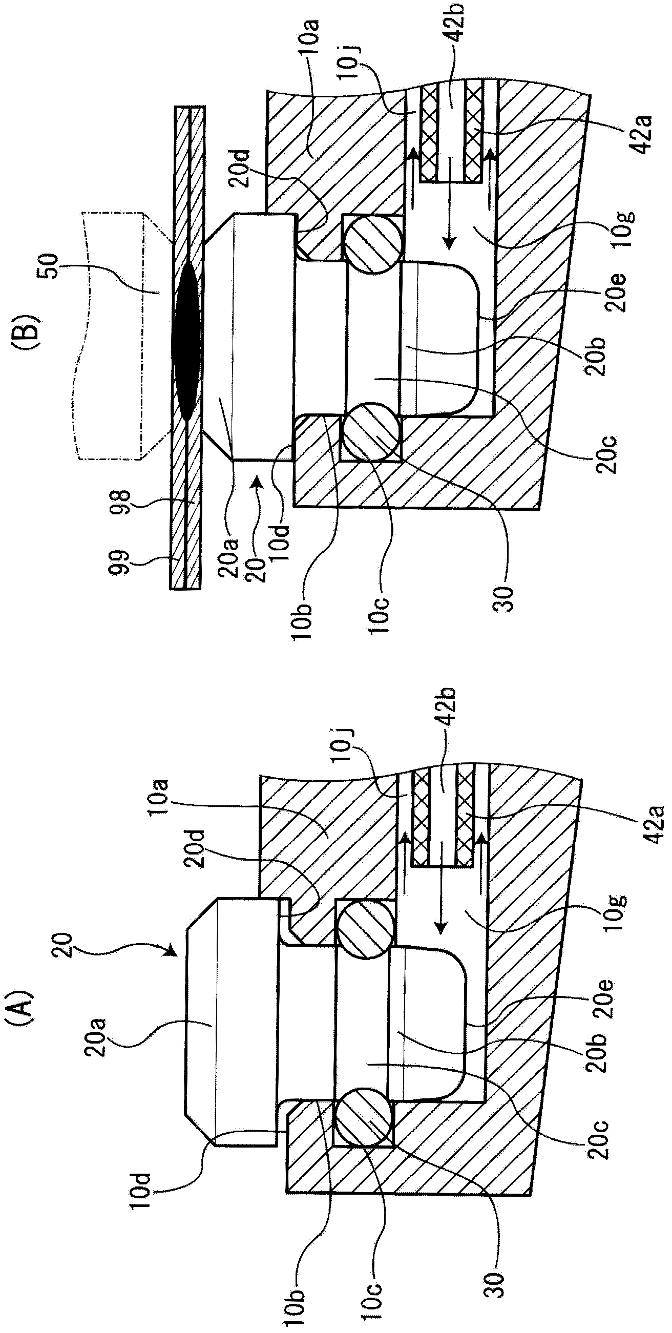
[0050] Below, with reference to accompanying drawing, accompanying drawing shows preferred embodiment of the present invention. 10 is an electrode frame, which is installed in the power supply part of the spot welding machine. The electrode holder 10 is supplied with welding current from the power supply unit described above. The electrode frame 10 is made of a tough copper alloy such as chromium copper and beryllium copper with good electrical conductivity. The electrode holder 10 is protrudingly formed with a plate-shaped protruding portion 10a. The surface of the protrusion 10a is recessed to form a mounting recess 10b. The cross-sectional shape of the mounting recess 10b is circular. The mounting recess 10b is not inclined with respect to the surface of the protrusion 10a, but is formed to perpendicularly intersect with the surface of the protrusion 10a. A first O-ring groove 10c is recessed and formed over the entire circumference of the inner peripheral surface of th...

no. 2 approach

[0061]The electrode part of the spot welding machine of 2nd Embodiment is demonstrated about the point which differs from 1st Embodiment. The electrode holder 110 of the second embodiment has a cylindrical shape. Such an electrode holder 110 is generally called a rod body. A cooling water passage 110 d is formed inside the electrode holder 110 . The top end of the electrode holder 110 is formed with a mounting recess 110a communicating with the cooling water passage 110d. The cross-sectional shape of the mounting recess 110a is circular. The mounting recess 110 a is not inclined with respect to the length direction of the electrode holder 110 . A first O-ring groove 110b is recessed and formed over the entire circumference of the inner peripheral surface of the mounting recessed portion 110a. A flat power supply surface 110 c is formed around the opening of the mounting recess 110 a at the tip of the electrode holder 110 . The power supply surface 110c perpendicularly int...


PUM


Abstract

Provided is a spot welder electrode part that can prevent overheating of an electrode holder and a small tip. A recessed mounting part (10b) with a circular cross-sectional shape is formed as a depression in the surface of a projecting part (10a) of an electrode holder (10), a first O-ring groove (10c) is formed in the inner circumferential surface of the recessed mounting part (10b), a cooling water channel (10g) connecting to the recessed mounting part (10b) is formed in the electrode holder (10), and a cylindrically-shaped mounting part (20b) is formed at the base end of a contact part (20a) of an electrode (20). A second O-ring groove (20c) is also formed in the outer circumferential surface of the mounting part (20b), the mounting part (20b) is connected to the inside of the recessed mounting part (10b), and an O-ring (30) is fit into the first O-ring groove (10c) and the second O-ring groove (20c) to mount the electrode (20) at the projecting part (10a). The electrode (20) and the projecting part (10a) are cooled by cooling water flowing inside the cooling water channel (10g).

Description

technical field [0001] The present invention relates to a structure of an electrode part of a spot welding machine. Background technique [0002] Conventionally, as disclosed in Patent Document 1, as one of the welding methods of metal parts, spot welding in which metal parts are crimped, energized, and metals are melted and joined by resistance heat is widely used. Such as Figure 5 As shown, the spot welding machine used for this spot welding has an electrode part 90, and the electrode part 90 consists of a pair of cylindrical rods 91 that can be separated from each other and connected, and a cap-shaped cap mounted on the top end of the pair of rods 91. Contact 95 constitutes. Spot welding is performed by crimping a metallic material with a pair of cap contacts 95 and energizing it. At the top end of the rod body 90 is formed a mounting portion 91 a whose diameter decreases toward the top end into a tapered shape. The cap-shaped contact 95 is recessed to form a mounting...

Claims


Application Information

Patent Timeline
Patent Type & Authority Applications(China)
IPC IPC(8): B23K11/31B23K11/30B23K11/36
CPCB23K11/3054B23K11/3018
Inventor 浅井直树蕗泽武夫
Owner SHINKOKIKI CO LTD
Why Eureka
Try Eureka