Transmitter with quantization noise compensation

A technology for quantizing noise and transmitter, applied in the field of transmitter, which can solve the problems of reducing transmitter power efficiency, increasing power consumption, large insertion loss, etc.

Inactive Publication Date: 2012-04-25
TELEFON AB LM ERICSSON (PUBL)
View PDF5 Cites 0 Cited by
  • Summary
  • Abstract
  • Description
  • Claims
  • Application Information

AI Technical Summary

Problems solved by technology

These types of filters have a large insertion loss at microwave frequencies, which results in...

Method used


Image

  • Transmitter with quantization noise compensation
  • Transmitter with quantization noise compensation
  • Transmitter with quantization noise compensation

Examples


Embodiment 600

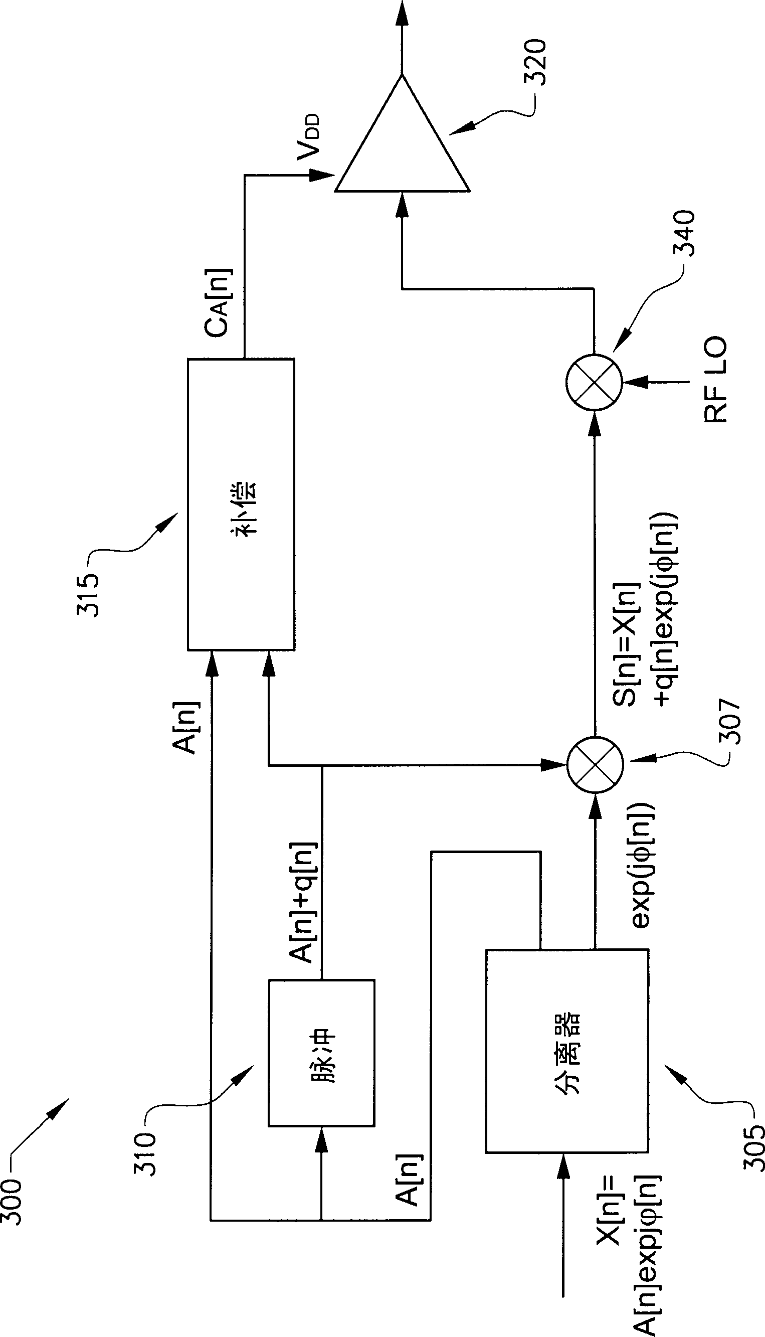
[0049] The compensation signal generator 315 of embodiment 600 has two input signals, one of which is the input signal x[n], and the other signal is the output from the mixer 307 (denoted S[n]). thus, Figure 5 The two input signals to the compensation signal generator 315 in are x[n] and Using the input signal x[n] as one of the input signals to the compensation signal generator 315 is achieved by "splitting" the input signal x[n] before the component separator 305, so that one "branch" of x[n] is related to the compensation The signal generator 315 is connected and the other "branch" of x[n] is used as the input signal to the signal component separator 305 .

[0050] As mentioned above, in Figure 5 In an embodiment of , the output S[n] from the mixer 307 is also split such that one "branch" of S[n] is used as an input to the compensation signal generator 315, and one "branch" of S[n] Used as an input to the first delay circuit 630 .

[0051] In contrast to the previo...


PUM


Abstract

The invention discloses a transmitter (300, 400, 600) comprising a pulse encoder (305) for creating pulses from the amplitude of an input signal to the transmitter, a compensation signal generator (315) for cancelling quantization noise caused by the pulse encoder (305), a mixer or I/Q modulator (307) for mixing an output of the pulse encoder with the phase of an input signal to the transmitter and an amplifier (320) for creating an output signal from the transmitter. In the transmitter (300, 400, 600), a control signal (CA) for controlling a function of the amplifier (320) comprises an output signal from the compensation signal generator (315), and an input signal to the amplifier (320) comprises an output from the mixer (307) having been modulated (340) to a desired frequency.

Description

technical field [0001] The present invention discloses a transmitter with improved efficiency. Background technique [0002] Transmitters typically include at least one amplifier, the efficiency of which can be enhanced by pulse modulation (ie, mapping the modulated communication signal to a characteristic of the pulse train, such as duration, position or density). In such transmitters, pulses are used as input to an amplifier. The purpose of driving the amplifier with a burst is to allow the amplifier to operate at its high efficiency operating point more of the time. By using bursts, the power amplifier is only operated in one of two high-efficiency regions (deeply compressed or completely off). [0003] However, pulse modulation schemes such as those described above will introduce undesired signal distortions due to quantization noise when generating pulses, which need to be dealt with by bandpass filters (so-called reconstruction filters). Due to the nature of quantiz...

Claims


Application Information

Patent Timeline
IPC IPC(8): H03F1/26H04L27/36
CPCH04L27/366H04L25/4902H03F1/0244H04B1/0475H04L27/361H03C1/00H03C2200/0058H03F3/24H03G3/3042H03G11/002H04B2001/0408H04B2001/0425H03F1/3241H03F1/3247H04L25/49
Inventor 乌尔夫·古斯塔夫松约翰·托雷贝克
Owner TELEFON AB LM ERICSSON (PUBL)
Why Eureka
Try Eureka