Nail cap support device

A technology of nail caps and cap holders, which is applied in the direction of hats, cap products, applications, etc., can solve the problems of being unable to meet large-scale large-scale production, time-consuming, laborious, and poor quality, and achieve consistent nail formation, accurate positioning, and easy operation. convenient effect

Inactive Publication Date: 2014-05-07
JIHUA 3534 CLOTHING
View PDF5 Cites 0 Cited by
  • Summary
  • Abstract
  • Description
  • Claims
  • Application Information

AI Technical Summary

Problems solved by technology

[0003] The purpose of the present invention is to solve the technical problems of time-consuming, labor-intensive, low efficiency, poor quality and inability to meet large-scale production in the existing manual rivet cap holders, and provide a time-saving, labor-saving, high-efficiency, high-quality product that can meet Nut and nut support device required for mass production
[0005] Since the present invention adopts the above-mentioned technical scheme, the technical problems of time-consuming, labor-intensive, low efficiency, poor quality and inability to meet large-scale mass production existing in the existing manual rivet cap holders are solved.

Method used


Image

  • Nail cap support device
  • Nail cap support device

Examples


Embodiment Construction

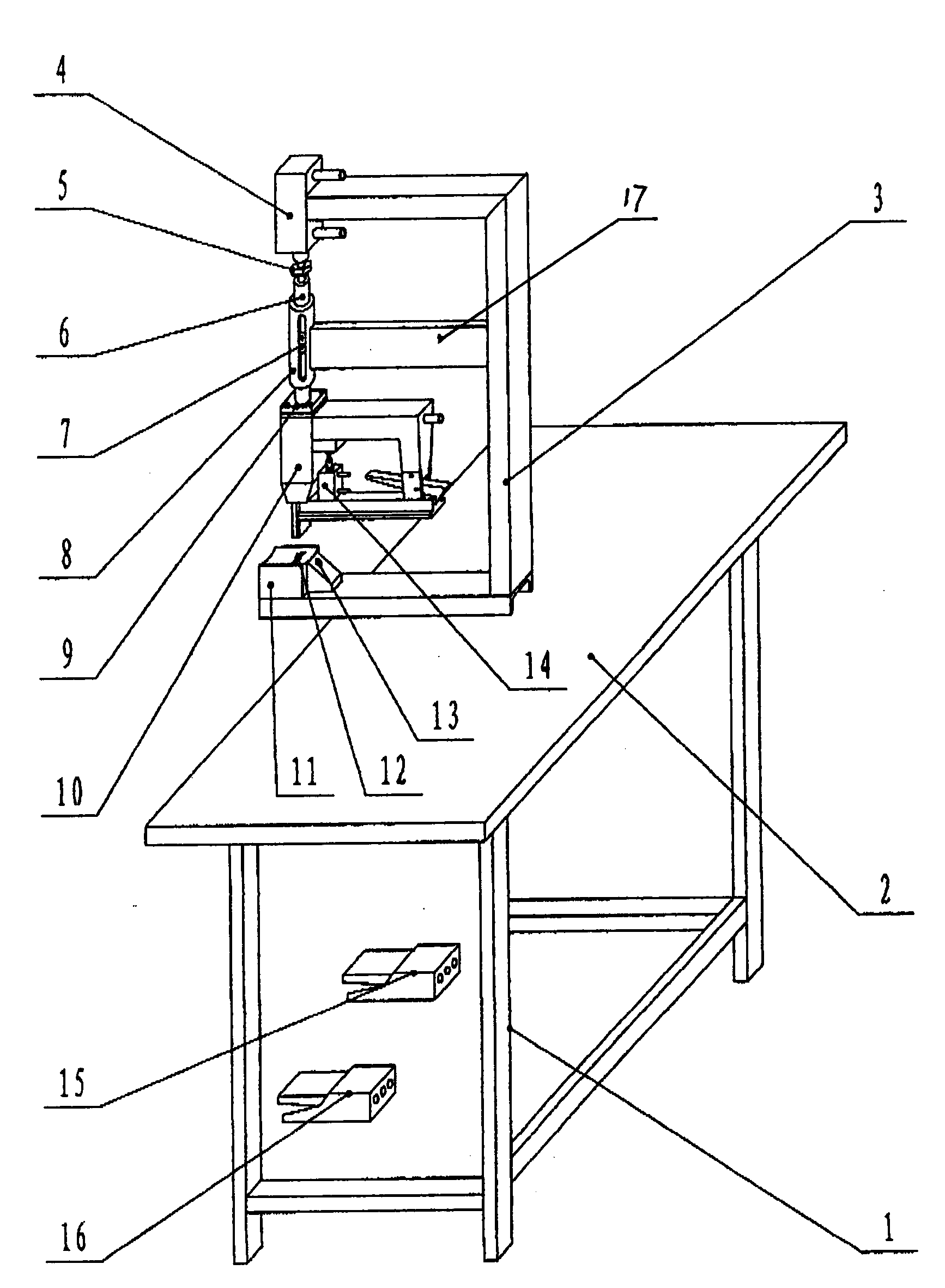
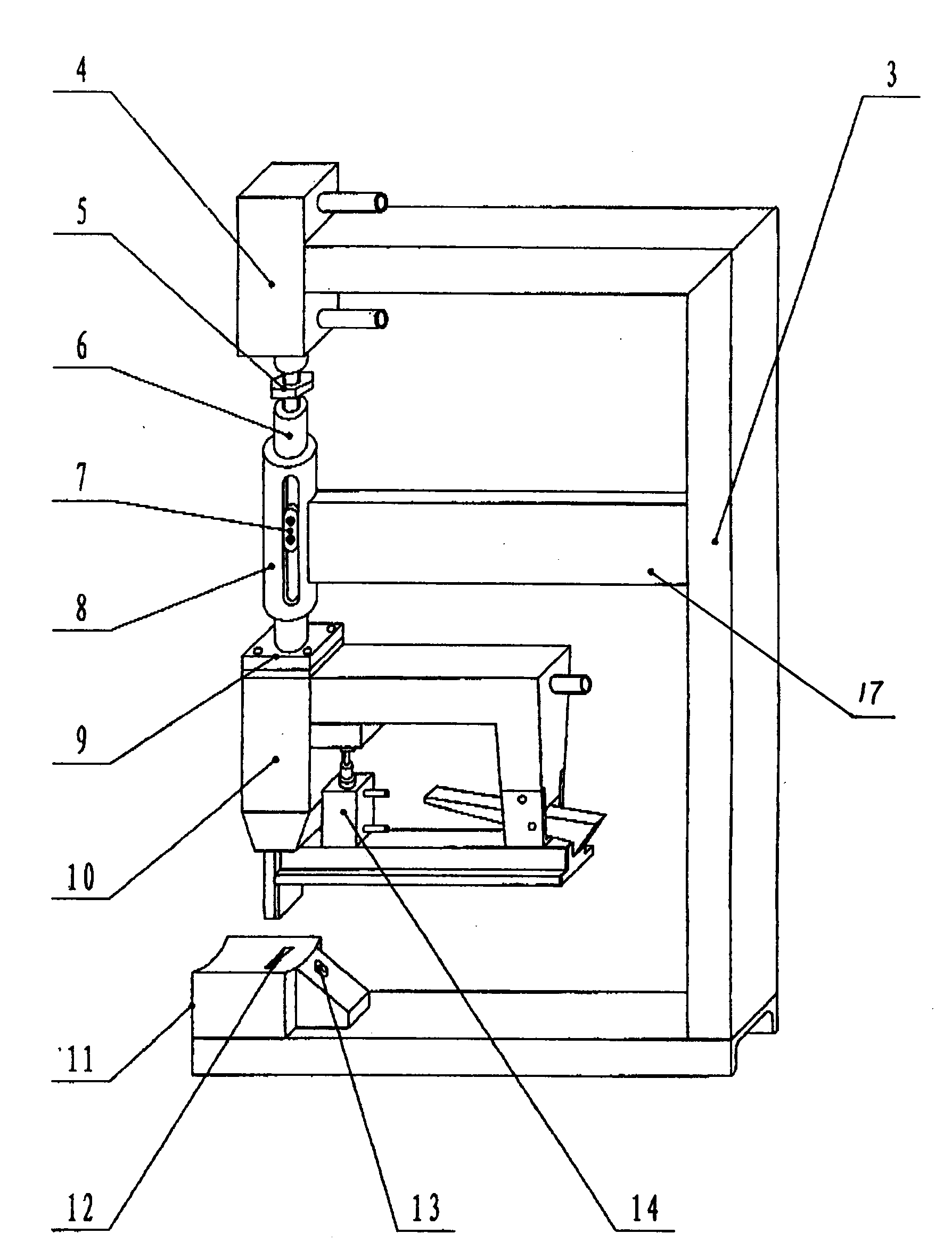
[0008] Such as figure 1 with figure 2 Shown, the nail nut support device among the present embodiment comprises frame 1, platen 2, left foot valve 15 and right foot valve 16, platen 2 is arranged on the upper end of frame 1, left foot valve 15 And right pedal valve 16 is located at the bottom of frame 1 front, wherein: it also includes by main frame 3, pressure gun cylinder 4, lock nut 5, main shaft 6, slide block 7, main shaft sleeve 8, connecting plate 9, pneumatic Code nail gun 10, cap holder seat 11, hat holder positioning block 13 and trigger cylinder 14 constitute the main body; pressure gun cylinder 4 is located on the top of main frame 3 and is connected with main frame 3 with bolts, and the piston rod of pressure gun cylinder 4 Connect with the main shaft 6 through a threaded buckle and fix it with the lock nut 5. The main shaft sleeve 8 is set outside the main shaft 6. The outer wall of the main shaft sleeve 8 is fixedly connected with the main frame 3 through the ...


PUM


Abstract

The invention relates to a nail cap support device, and belongs to equipment for producing nail cap supports for big rimmed caps. The nail cap support device mainly solves the technical problems of time and labor waste, low efficiency and poor quality in the conventional manual rivet cap supports. According to the technical scheme, the nail cap support device comprises a frame, a bedplate, a left foot valve, a right foot valve and a main machine body, wherein the main machine body consists of a main frame, a pressure gun cylinder, a lock nut, a main shaft, a sliding block, a main shaft sleeve, a connecting plate, a pneumatic code nail gun, a cap support seat, a cap support positioning block and a trigger cylinder; the pressure gun cylinder is arranged on the upper part of the main frame, a piston rod of the pressure gun cylinder is connected with the main shaft through a screw buckle, the main shaft sleeve is arranged outside the main shaft, and the sliding block is arranged on the middle part of the main shaft and positioned in a slipway of the main shaft sleeve; the lower end of the main shaft is provided with the connecting plate which is connected with the top of the pneumatic code nail gun, and the cap support seat is arranged on a bracket on the lower part of the main frame; and the cap support positioning block is arranged on the inclined plane of the rear part of the cap support seat.

Description

technical field [0001] The invention relates to a nail nut holder device, which belongs to a kind of equipment for producing nail hat holders used for large brim hats. Background technique [0002] In the process of producing large-brimmed hats, according to the technical requirements, it is necessary to use row nails to connect the hat holder and the hat wall together. In the past, the nails were passed through the hat holder and the hat wall by hand with a pneumatic nail gun, and then Bending and flattening the two nail feet that pass through the hat bracket and the hat wall by hand is time-consuming, laborious, and inefficient, and the positions of the hat bracket, hat wall, and nails are not easy to fix, and the repair rate and scrap rate are extremely high, making it difficult to Guarantee product quality, can't meet the needs of large-scale large-scale production. Contents of the invention [0003] The purpose of the present invention is to solve the technical probl...

Claims


Application Information

Patent Timeline
Patent Type & Authority Patents(China)
IPC IPC(8): A42C3/00
Inventor 石俊英孙全义王宗茹高永亮
Owner JIHUA 3534 CLOTHING
Why Eureka
Try Eureka