

Continuous cooling crystallizer
A technology of cooling crystallization and crystallization tank, which is applied in the direction of solution crystallization, etc., can solve the problems of easy scaling, wear and tear, and large heat transfer coefficient of external heat exchangers, and achieve the effects of stable operation, difficult scaling, and simple equipment structure
Inactive Publication Date: 2012-05-02
ZHEJIANG HUAYI ENG DESIGN
View PDF4 Cites 14 Cited by
- Summary
- Abstract
- Description
- Claims
- Application Information
AI Technical Summary
Problems solved by technology
The heat transfer coefficient is large and the heat transfer area is variable, but a suitable circulating pump must be selecte
Method used
View moreImage
Smart ImageViewing Examples


Examples
 PUM
 Abstract
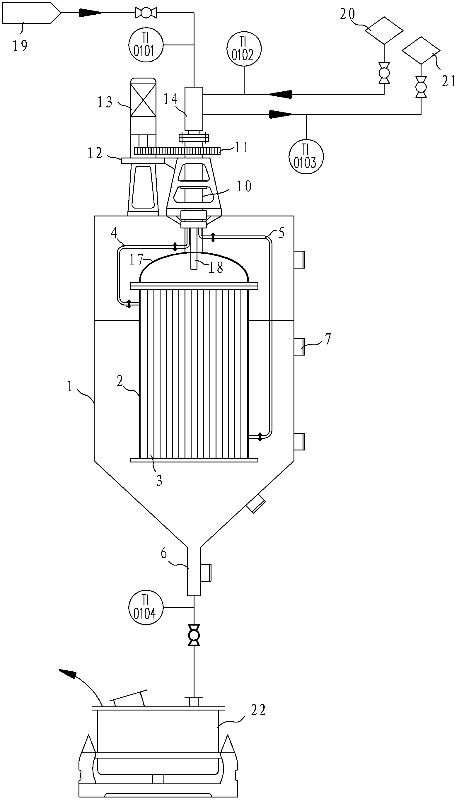
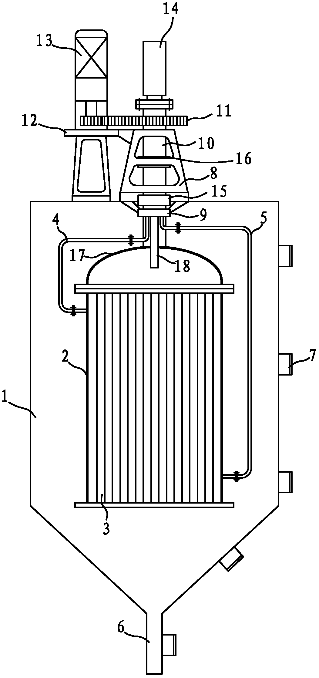
The invention discloses a continuous cooling crystallizer, comprising a crystallization tank and a heat exchanger in the crystallization tank, wherein, the heat exchanger comprises a top-enclosed heat exchange cylinder, a heat exchange pipe fixed in the heat exchange cylinder, a cooling medium inlet pipe and a cooling medium outlet pipe; a hollow shaft vertically passing through the top surface of the crystallization tank and a driving mechanism driving the hollow shaft to rotate are arranged above the crystallization tank, the top end of the hollow shaft is connected with a three-channel rotary joint, the bottom end of the hollow shaft is connected with the enclosed end of the heat exchange cylinder; a material pipe which has a top end communicated with one channel of the three-channel rotary joint and a bottom end passing through the heat exchange cylinder is arranged in the hollow shaft, one ends of the cooling medium inlet pipe and the cooling medium outlet pipe are respectively communicated with the inlet end and outlet end of the heat exchange pipe, and the other ends of the cooling medium inlet pipe and the cooling medium outlet pipe are respectively communicated with the rest two channels of the three-channel rotary joint. The continuous cooling crystallizer is used in a cooled shell-and-tube heat exchanger and arranged in the crystallization tank, rotates at a certain speed when working, and the cooling process and stirring process are combined as a whole, thus the crystallization efficiency is greatly increased.
Description
technical field [0001] The invention relates to chemical equipment, in particular to a continuous cooling crystallizer. Background technique [0002] Cooling crystallization is a process in which the solubility of the solute is reduced to become a supersaturated solution by cooling the solution, and the solute is precipitated. It is suitable for substances whose solubility decreases significantly as the temperature decreases. It can obtain very pure crystal products from solutions with high impurity content, and is suitable for many difficult-to-separate mixture systems, isomer systems and heat-sensitive systems. Substances with the same chemical composition can crystallize into two or more crystals with different structures under different physical and chemical conditions, and these crystals have different physical and chemical properties. Therefore, the control of crystallization parameters is very critical in chemical production. [0003] Existing solution crystallizatio...
Claims
Login to View More Application Information
Patent Timeline
 IPC IPC(8): B01D9/02
Inventor赵军辉吴荔荔徐伟松
OwnerZHEJIANG HUAYI ENG DESIGN