Multiroll mill stand processing method and fixture device

A rolling mill and stand technology, which is applied in the field of multi-roll mill stand processing methods and tooling devices, can solve the problems of inability to meet the multi-roll mill rolling operation accuracy requirements, and achieves simple structure, high machining accuracy, and optimal boring. The effect of precision

Active Publication Date: 2012-05-02
MCC CAPITAL ENGINEERING & RESEARCH +1
View PDF9 Cites 7 Cited by
  • Summary
  • Abstract
  • Description
  • Claims
  • Application Information

AI Technical Summary

Problems solved by technology

The parallelism tolerance of the processed 8 boring arcs can only meet 0.05-0.1mm / M, which cannot meet the precision requirements of the multi-roll mill rolling operation

Method used


Image

  • Multiroll mill stand processing method and fixture device
  • Multiroll mill stand processing method and fixture device
  • Multiroll mill stand processing method and fixture device

Examples


Embodiment Construction

[0040] In order to have a clearer understanding of the technical features, purposes and effects of the present invention, the specific implementation manners of the present invention will now be described with reference to the accompanying drawings.

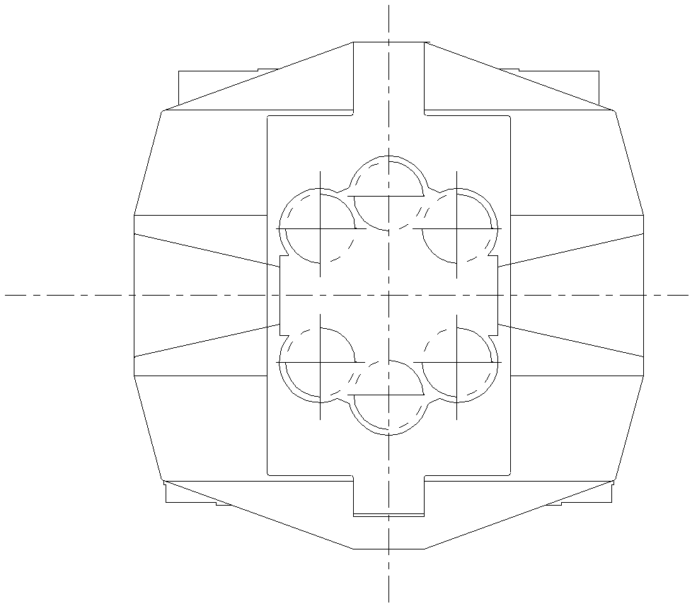
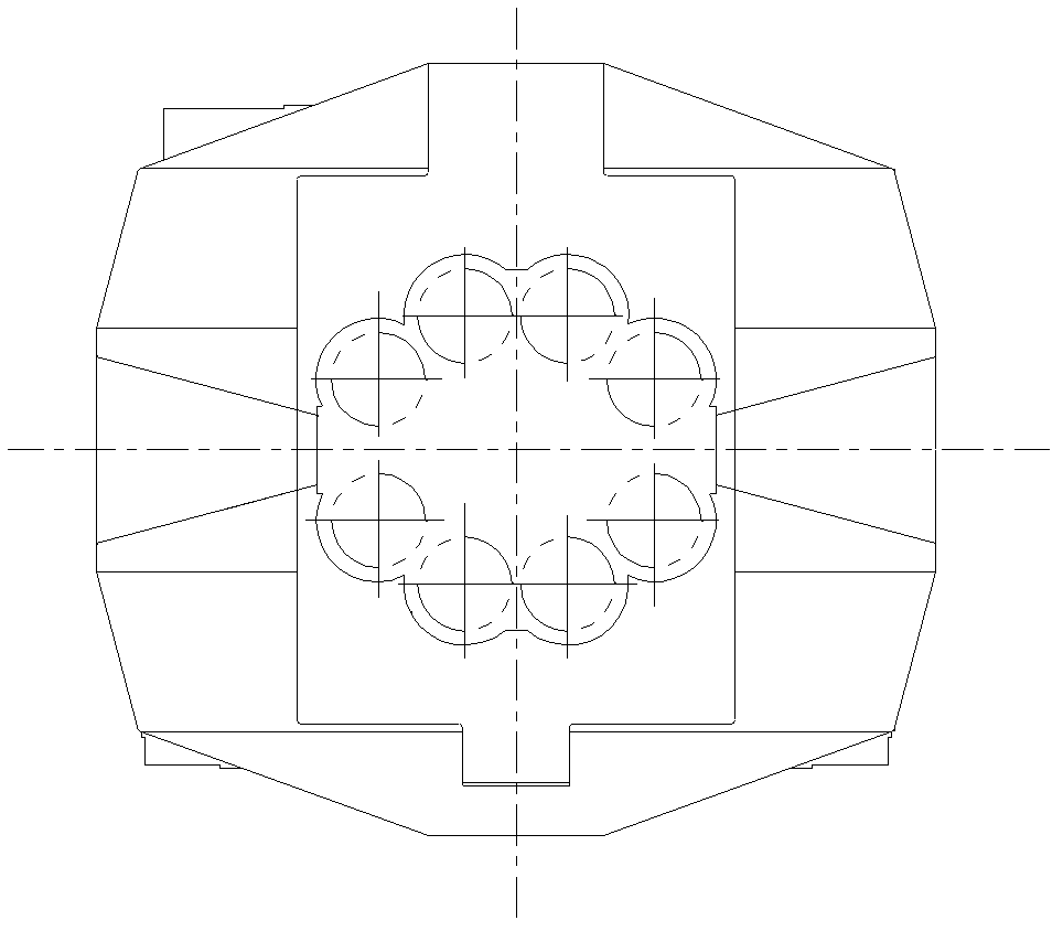
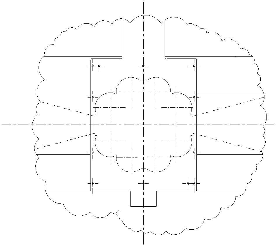
[0041] Please refer to Figure 4 , Figure 5 , are respectively the structural schematic diagram of the tooling device used for processing multi-roll rolling mill racks of the present invention in use and the structural schematic diagram of the boring die of the tooling device of the present invention. like Figure 4As shown, the tooling device proposed by the present invention for processing the multi-roll mill frame 100 is driven by the boring shaft 6 on one side of the boring machine 1, and includes a floating boring bar 2, a left boring die 3, a right boring die 4 and a boring tool Component 5, one end of the floating boring bar 2 is detachably connected with the boring shaft 6 through the cardan shaft 7, and the floating b...


PUM


Abstract

The invention discloses a fixture device and method for processing multiroll mill stand. The driving is done by a boring shaft at one side of a boring machine. The fixture device comprises a floating boring rod one end of which is detachably connected with the boring shaft by a cardan shaft, wherein the floating boring rod is penetrated into a boring hole to be fine processed on the multiroll mill stand; two boring moulds symmetrically provided and fixed at two sides of the stand and located at two end sides of the boring hole, wherein multiple pairs of positioning holes are opened on the twoboring moulds parallel to the axial direction of the boring hole, the positions of the positioning holes are corresponding to the face to be fine processed on internal wall of the boring hole, and the floating boring rod can be penetrated between a corresponding pair of positioning holes on the two boring moulds movably; and at least one boring cutter assembly inserted on an installing slot opened on the floating boring rod radially, wherein upper part of the boring cutter assembly is provided with blades projected out of the floating boring rod and in contact with the face to be fine processed. The invention can meet precision requirement of the multiroll mill stand processing with simple structure, easy operation and convenient use.

Description

technical field [0001] The invention relates to the field of steel rolling processing and devices, in particular to a multi-roll mill frame processing method and tooling device for rolling thin or difficult-to-roll metal strips. Background technique [0002] At present, multi-roll mills are widely used in the world to roll stainless steel, silicon steel and high-strength metal and alloy thin strips. The roll system of the existing multi-roll rolling mill is a tower-shaped roll system, and the tower-shaped roll system makes the rolling force be transmitted to the outer support roll in a fan shape, and then transmitted to the frame by multiple fulcrums of the support roll. The more layers of tower-shaped rollers, the more outer layer support rolls, so that the rolling load of the rolling mill is transmitted to the stand through multiple fulcrums of the support rolls of the roll system. like figure 1 , figure 2 As shown, it is a side view structural schematic diagram of two...

Claims


Application Information

Patent Timeline
Patent Type & Authority Applications(China)
IPC IPC(8): B23B41/00B23B35/00
Inventor 韩培恋陈南宁李新张景智陈钢
Owner MCC CAPITAL ENGINEERING & RESEARCH
Why Eureka
Try Eureka