Heat-dissipating method of LED (Light-Emitting Diode) heat-dissipating module and LED heat-dissipating module

A technology of LED modules and heat dissipation modules, applied in lighting and heating equipment, components of lighting devices, cooling/heating devices of lighting devices, etc., can solve the problems of shortened service life, high cost, and excessive use of materials. Achieve the effect of reducing the speed of light decay, solving heat dissipation problems, and increasing the heat dissipation area

Active Publication Date: 2012-05-02
DONGGUAN PERFECT SCI & TECH
View PDF4 Cites 2 Cited by
  • Summary
  • Abstract
  • Description
  • Claims
  • Application Information

AI Technical Summary

Problems solved by technology

Excessive chip temperature will bring many problems, such as accelerating device aging, accelerating the speed of LED light decay, shortening the service life, and even causing the chip to burn
[0004] At present, the heat sinks for LED heat dissipation on the market are usually extruded, die-casted, machined or cut to solve the heat dissipation. Generally, they are large in size, heavy in weight, use more materials, and have high cost. Those who do not have enough understanding of thermal conduction, heat convection and heat radiation, the designed radiators are often not very reasonable, so many problems are caused, such as heat conduction is good, but heat convection is not good; heat convection is good, heat conduction is not good , has a great impact on the heat dissipation of LED light sources. For example, the weight of LED lamps cannot be effectively reduced, the heat dissipation problem of LED lamps cannot be solved well, and it is difficult to achieve high-power LED lamps. The service life of LED also has a great influence

Method used


Image

  • Heat-dissipating method of LED (Light-Emitting Diode) heat-dissipating module and LED heat-dissipating module
  • Heat-dissipating method of LED (Light-Emitting Diode) heat-dissipating module and LED heat-dissipating module
  • Heat-dissipating method of LED (Light-Emitting Diode) heat-dissipating module and LED heat-dissipating module

Examples


Embodiment

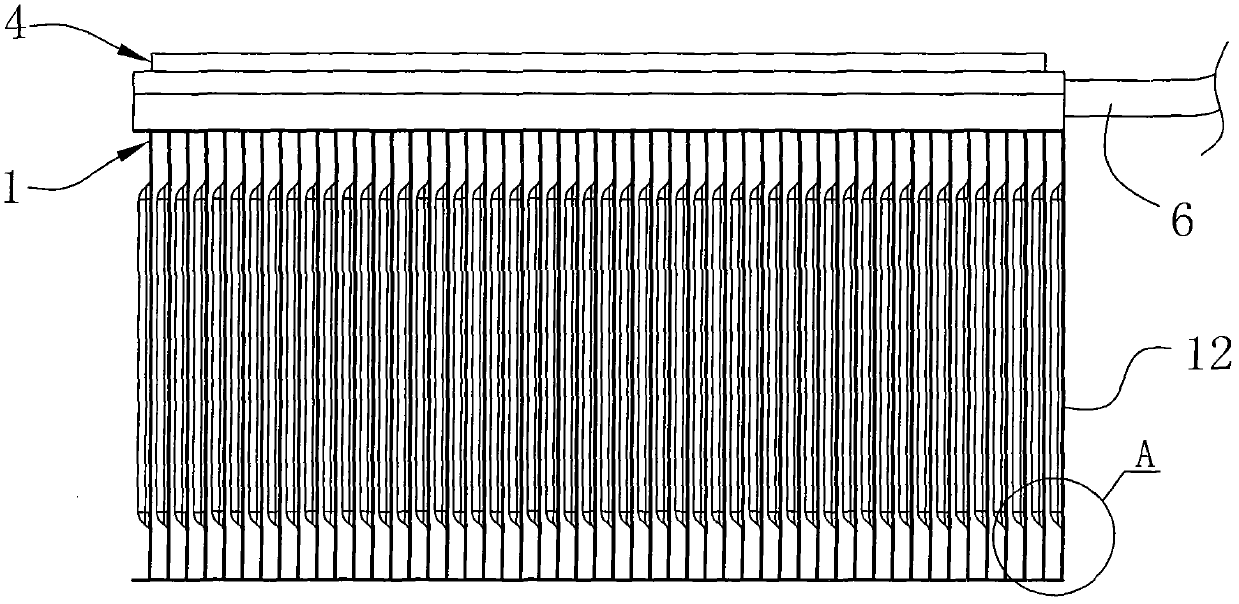
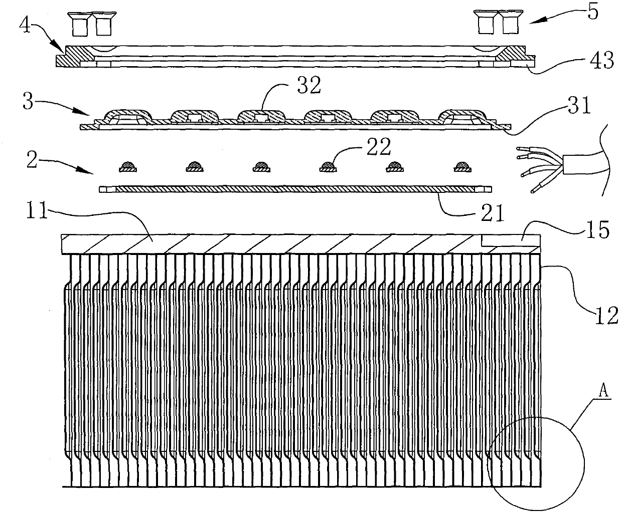
[0032] Example: see Figure 1 to Figure 4 , an embodiment of the present invention provides a heat dissipation method for an LED heat dissipation module, which includes the following steps:

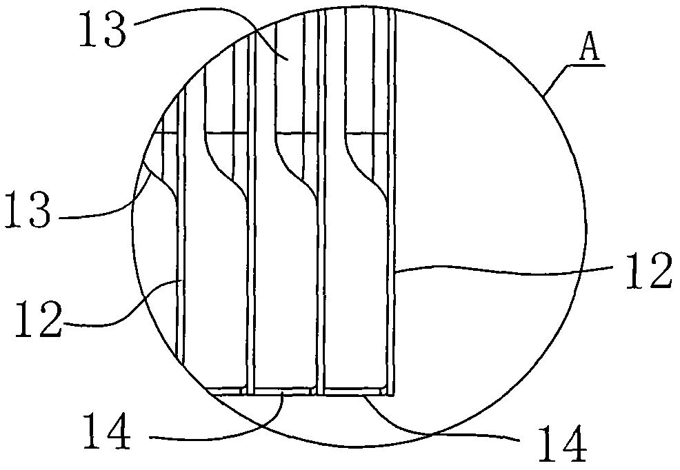
[0033] (1) Preparation of cooling fins 12: prepare sheet metal material, punch it, punch it, and shape it to produce a plurality of cooling fins 12, and the middle part of each cooling fin 12 has multiple rows side by side to enhance its structural strength and increase The heat dissipation area and the elongated vertical protrusion 13 for improving the heat dissipation effect, the top of the heat sink 12 is provided with an insertion part, and the bottom edge of the heat sink 12 is provided with at least one fixed foot 14;

[0034](2) Preparation of heat dissipation bottom plate 11: prepare plate-shaped metal material, punch it, drill holes, and shape it to produce a heat dissipation bottom plate 11, and on the bottom surface of the heat dissipation bottom plate 11, there are a plurality...


PUM


Abstract

The invention discloses a heat-dissipating method of an LED (Light-Emitting Diode) heat-dissipating module. The LED heat-dissipating module comprises a heat-dissipating module, an LED module, an optical lens module and a cover plate which are laminated in sequence. By adopting the method provided by the invention, heat of an LED lamp can be dissipated, so that the light decay speed is lowered, and the service life is prolonged. The invention further discloses an LED heat-dissipating module for implanting the method. The LED heat-dissipating module has a reasonable structure, is made of a preferred aluminum material, and has light weight; moreover, radiating fins are provided with strip-shaped vertical bumps which can be used for enhancing the structural strength, increasing the heat-dissipating area and improving the heat-dissipating effect; furthermore, two adjacent radiating fins are fixed together through a fixing pin, so that high stability is achieved; and a ventilation groove isformed between every two adjacent radiating fins for ventilating, so that heat of the LED lamp can be dissipated quickly, the light decay speed is lowered, and the service life is prolonged greatly.

Description

technical field [0001] The invention relates to a lighting fixture manufacturing technology, in particular to an efficient and environment-friendly heat dissipation method for an LED heat dissipation module and the LED heat dissipation module. Background technique [0002] Most of the traditional road lamps use high-power mercury lamps, metal halide lamps or high-pressure sodium lamps as light sources. High, lighting effects are unsatisfactory in terms of color rendering and anti-glare performance. At the same time, the development of semiconductor light-emitting diodes (LEDs) is extremely rapid. In recent years, the luminous efficiency of some LEDs has greatly exceeded that of incandescent lamps, and even exceeded that of fluorescent lamps. Compared with the traditional floodlight electric light source, the LED light source is basically non-toxic, non-electromagnetic pollution, and has many advantages such as small size, low energy consumption, high luminous efficiency, re...

Claims


Application Information

Patent Timeline
Patent Type & Authority Applications(China)
IPC IPC(8): F21V29/00F21V17/12F21V19/00F21Y101/02F21V29/74
Inventor 安波滔
Owner DONGGUAN PERFECT SCI & TECH
Why Eureka
Try Eureka