Method and device for quickly forming arc for leading wire by using wire clamp to manufacture salient points

A technology of quick leads and bent leads, which is applied in semiconductor/solid-state device manufacturing, electrical components, electric solid-state devices, etc., can solve problems such as low work efficiency and complex rivet trajectory, and achieve simple rivet trajectory and simple working process , the effect of avoiding damage

Inactive Publication Date: 2012-05-02
CENT SOUTH UNIV
View PDF12 Cites 7 Cited by
  • Summary
  • Abstract
  • Description
  • Claims
  • Application Information

AI Technical Summary

Problems solved by technology

[0006] The technical problem to be solved by the present invention is to provide a method and device for fast lead arc forming using wire clips to manufacture inflection points. The rapid lead arc forming method a

Method used


Image

  • Method and device for quickly forming arc for leading wire by using wire clamp to manufacture salient points
  • Method and device for quickly forming arc for leading wire by using wire clamp to manufacture salient points
  • Method and device for quickly forming arc for leading wire by using wire clamp to manufacture salient points

Examples


Embodiment 1

[0043] Example 1: M-line arc process

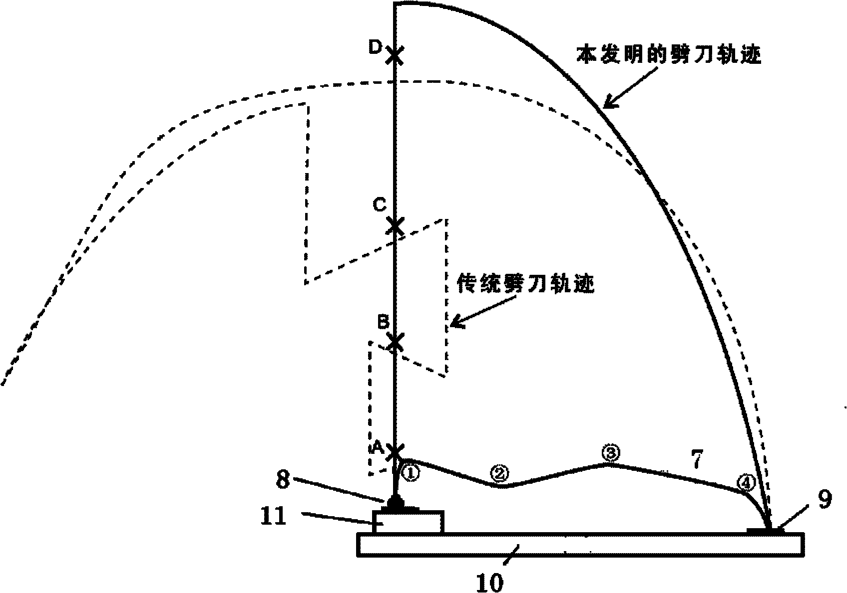
[0044] The forming method of the M line arc mentioned in the present invention will be based on figure 2 to describe.

[0045] The process of wire bonding consists of three steps:

[0046] 1) The first step is the same as the traditional wire bonding process, the wire passing through the capillary forms a solder ball at the tip of the capillary and is soldered to a solder point.

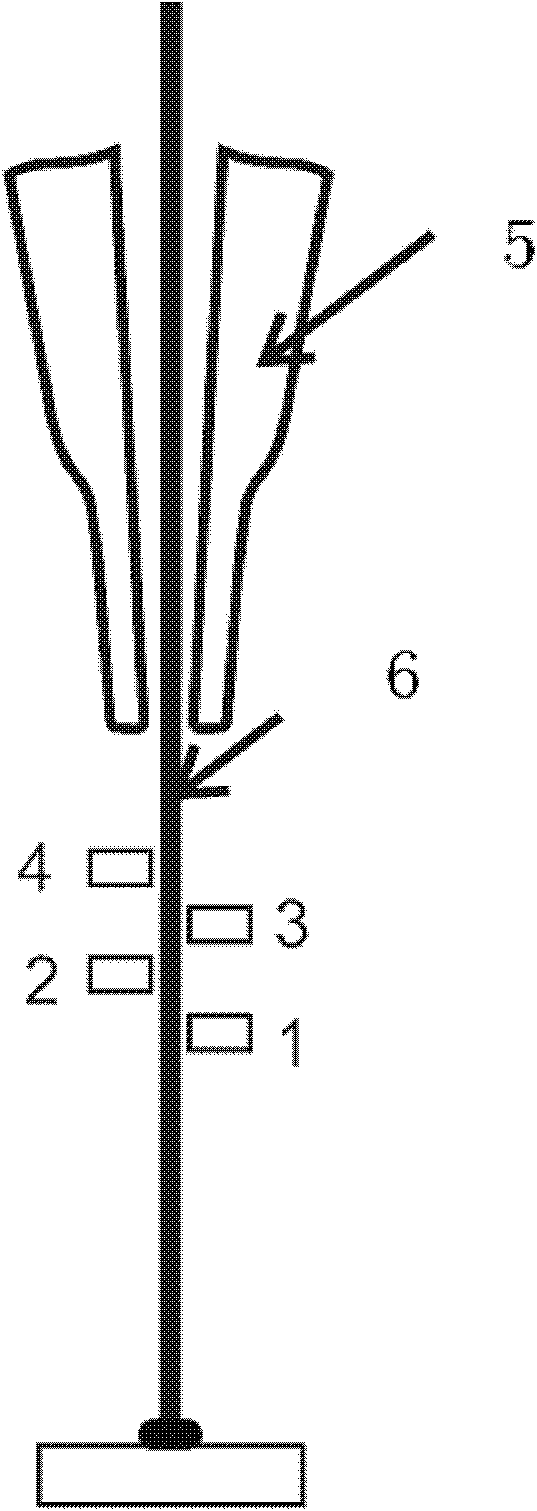
[0047] 2) Then, the capillary rises to the position of point A (130 microns away from the pad) and pauses, and moves into the line clip for manufacturing the folding point to 20 microns below the capillary. At this time, the bonding system sends an instruction to the wire clamp to move the movable arm 2 horizontally to create a left concave inflection point; similarly, move the wire clamp to point B (600 microns away from the pad) to create a right convex inflection point; move the wire Clamp to point C (1200 microns away from the pad) and pause at the crosse...

Embodiment 2

[0050] Embodiment 2: the formation process of STD line type

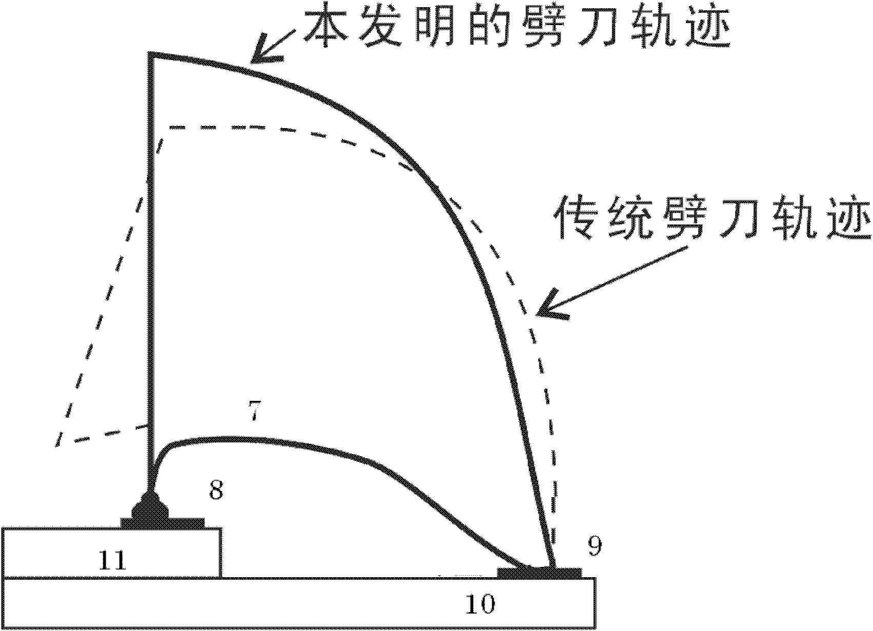
[0051] The STD line type is the most basic arc in wire bonding and contains only one inflection point. Utilize the method that the present invention forms STD linear pattern as Fig. 4, and its manufacturing process is:

[0052] 1) The first step is the same as the traditional wire bonding process, the wire passing through the capillary forms a solder ball at the tip of the capillary and is soldered to a solder point.

[0053] 2) Then, the capillary rises to the position of point A (130 microns away from the pad) and pauses, and moves into the line clip for manufacturing the folding point to 20 microns below the capillary. At this time, the bonding system sends an instruction to the clamp to move the movable arm 2 horizontally to create a left concave inflection point.

[0054] 3) The riving knife continues to rise to the highest position (1400 microns away from the welding pad), then stop the wire supply, remove t...


PUM


Abstract

The invention discloses a method and a device for quickly forming an arc for a leading wire by using a wire clamp to manufacture salient points. The method comprises the following steps of: 1, forming a first welding spot on a chip bonding pad, then fixing a free end of the leading wire by a cleaver, and clamping and bending the leading wire between the cleaver and the first welding spot by using the wire clamp so as to form a series of salient points; 2, in the operational process of bending the leading wire, staggering two fixed arms at an upper position and a lower position, arranging the two fixed arms on two sides of the wire clamp respectively to clamp the leading wire, staggering two movable arms at an upper position and a lower position, and arranging the two movable arms on two sides of the wire clamp; and 3, loosening the wire clamp, driving the leading wire to move by the cleaver to weld the free end of the leading wire on a second bonding pad so as to finish the process of forming the arc for the leading wire. When the method and the device for quickly forming the arc for the leading wire by using the wire clamp are used to manufacture the salient points, the problems of complex cleaver tracks and low working efficiency in the conventional leading wire forming method can be solved.

Description

technical field [0001] The present invention relates to a method and device for fast lead wire arc forming by using wire clips to make fold points, in particular, using the action of wire clips to make one or more fold points on leads such as gold wires to form lead wire arcs of a specific arc shape Methods and Apparatus. Background technique [0002] Integrated circuit (IC) manufacturing is one of the core industries of high technology. Thermosonic wire bonding in microelectronic packaging is one of the most time-consuming and cost-intensive aspects of the IC manufacturing industry. Taking the complex M-arc as an example, a typical wire bonding process is as follows figure 2 The traditional rivet trajectory in , which refers to the use of ultrasonic, heat, force and other external field energy to bond the lead (typically gold wire) to the chip pad, and then use the movement trajectory of the rivet in space (the dotted line in the figure The trajectory of the chopper show...

Claims


Application Information

Patent Timeline
IPC IPC(8): H01L21/768
CPCH01L2224/78301H01L2224/48091H01L2224/48465H01L24/85H01L2224/85181H01L2224/85H01L2224/85205H01L2224/85207H01L2924/14H01L2924/00014H01L2924/00H01L2924/00012
Inventor 王福亮陈云韩雷李军辉
Owner CENT SOUTH UNIV
Why Eureka
Try Eureka