Topological circuit of inverter and inversion method thereof, and inverter

A topology circuit and inverter technology, applied in the field of communication, can solve the problems of turn-on and turn-off loss, low efficiency, and high power consumption of the circuit

Active Publication Date: 2012-05-02
HUAWEI DIGITAL POWER TECH CO LTD
View PDF5 Cites 27 Cited by
  • Summary
  • Abstract
  • Description
  • Claims
  • Application Information

AI Technical Summary

Problems solved by technology

[0003] When the inverter circuit is working, the high-frequency switch in the circuit needs to perform high-frequency switching between the on and off states, but in the prior art, when the switch performs high-frequency switching between on and off, it will Generate turn-on and turn-off losses
Therefore, the circuit consumes a lot of power and has low efficiency

Method used


Image

  • Topological circuit of inverter and inversion method thereof, and inverter
  • Topological circuit of inverter and inversion method thereof, and inverter
  • Topological circuit of inverter and inversion method thereof, and inverter

Examples


Embodiment 1

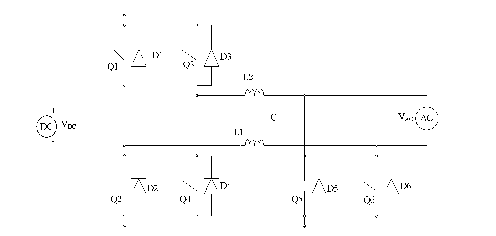
[0072] Embodiments of the present invention provide an inverter topology circuit, such as Figure 3A As shown, including DC source DC, AC source AC, high-frequency switch tubes Q1, Q2, Q3, Q4, power frequency switch tubes Q5, Q6, high-frequency filter inductors L1, L2, auxiliary conduction diodes D1, D2, D3, D4, D5, D6 and filter capacitor C.

[0073] Specifically, Q1 is connected in parallel with D1, Q2 is connected in parallel with D2, Q3 is connected in parallel with D3, Q4 is connected in parallel with D4, D1 and D2 are connected in series to form the first branch of the first bridge arm, and D3 and D4 are connected in series to form the second branch of the first bridge arm. The two branches are connected in parallel at the two poles of the DC source, where the cathodes of D1 and D3 are connected to the positive pole of DC, and the anodes of D2 and D4 are connected to the negative pole of DC.

[0074] One end of L1 is connected to the connection point between D1 and D2, ...

Embodiment 2

[0079] The inverter topology circuit provided by the embodiment of the present invention, such as Figure 3B As shown, including DC source DC, AC source AC, high-frequency switch tubes Q1, Q2, Q3, Q4, power frequency switch tubes Q5, Q6, high-frequency filter inductors L1, L2, auxiliary conduction diodes D1, D2, D3, D4, D5, D6 and filter capacitor C.

[0080] In this embodiment, only the cathodes of D5 and D6 are connected to the positive pole of the DC source, the anode of D5 is connected to the connection point between the second inductor and the AC source, and the anode of D6 is connected to the first inductor and the AC source. As for the connection point of the source, the remaining parts are completely the same as those in Embodiment 1, and will not be repeated here.

[0081] Among them, the DC source can be a fuel cell, nickel-hydrogen battery, iron battery, lead-acid battery, solar panel and other devices that provide DC; the switch tube can be MOSFET, IGBT, triode, t...

Embodiment 3

[0084] Embodiments of the present invention provide an inverter topology circuit, such as Figure 4A As shown, including DC source DC, AC source AC, high-frequency switching tubes Q1, Q2, Q3, Q4, power frequency switching tubes Q5, Q6, high-frequency filter inductors L1, L2, power frequency inductors L3, L4, and resonance suppression Resistor R, auxiliary conduction diodes D1, D2, D3, D4, D5, D6 and filter capacitor C.

[0085] Specifically, Q1 is connected in parallel with D1, Q2 is connected in parallel with D2, Q3 is connected in parallel with D3, Q4 is connected in parallel with D4, D1 and D2 are connected in series to form the first branch of the first bridge arm, and D3 and D4 are connected in series to form the second branch of the first bridge arm. The two branches are connected in parallel at the two poles of the DC source, where the cathodes of D1 and D3 are connected to the positive pole of DC, and the anodes of D2 and D4 are connected to the negative pole of DC.

...


PUM


Abstract

The embodiment of the invention, which belongs to the energy field, provides a topological circuit of an inverter and an inversion method thereof, and an inverter. Therefore, losses on opening and turning off of a high frequency switch can be prevented; working efficiency and a utilization rate of electric energy can be enhanced; a wide-range voltage input is realized; and a common-mode leakage current generated by a circuit of an inverter can be prevented, thereby improving security. The topological circuit of an inverter is characterized in that: a fifth switching tube, a sixth switching tube, a fifth diode, a sixth diode, and a first capacitor are added on a current inversion circuit containing a bridge arm; the fifth switching tube is in parallel connection with the fifth diode; and the sixth switching tube is in parallel connection with the sixth diode. Besides, an anode of the fifth diode is connected with a cathode of a direct current source as well as a cathode of the fifth diode is connected to a connection circuit between a second inductor and an alternative current source; and an anode of the sixth diode is connected with the cathode of the direct current source as well as a cathode of the sixth diode is connected to a connection circuit between a first inductor and the alternative current source. The embodiment of the invention is used for manufacturing of an inverter.

Description

technical field [0001] The invention relates to the communication field, in particular to an inverter topology circuit, an inverter method and an inverter. Background technique [0002] The inverter circuit is a circuit that converts direct current into alternating current, and is a circuit that converts direct current energy into alternating current energy; it includes the form of output alternating voltage, such as uninterruptible power supply, etc.; it also includes following the external alternating voltage to provide alternating current output The form of current, such as solar grid-connected inverters, wind-powered grid-connected generators, etc. [0003] When the inverter circuit is working, the high-frequency switch in the circuit needs to perform high-frequency switching between the on and off states, but in the prior art, when the switch performs high-frequency switching between on and off, it will Turn-on and turn-off losses occur. Therefore, the circuit consume...

Claims


Application Information

Patent Timeline
Patent Type & Authority Applications(China)
IPC IPC(8): H02M7/521
CPCH02M7/48H02M7/521H02M7/44
Inventor 张彦忠
Owner HUAWEI DIGITAL POWER TECH CO LTD
Why Eureka
Try Eureka