
Rotor disk

A technology of rotor disk and disk body, which is applied in the direction of mixer with rotating stirring device, mixer, transportation and packaging, etc., to achieve the effect of high running stability

Inactive Publication Date: 2012-05-02
EREMA ENG RECYCLING MASCH & ANLAGEN GMBH
View PDF7 Cites 3 Cited by
  • Summary
  • Abstract
  • Description
  • Claims
  • Application Information

AI Technical Summary

Problems solved by technology

[0007] When developing such devices it has been shown that the delivery power of the known disks (which still function adequately for smaller accumulators) is no longer sufficient for large accumulators to keep the material away from rough areas

Method used


Image

  • Rotor disk
  • Rotor disk
  • Rotor disk

Examples


Embodiment Construction

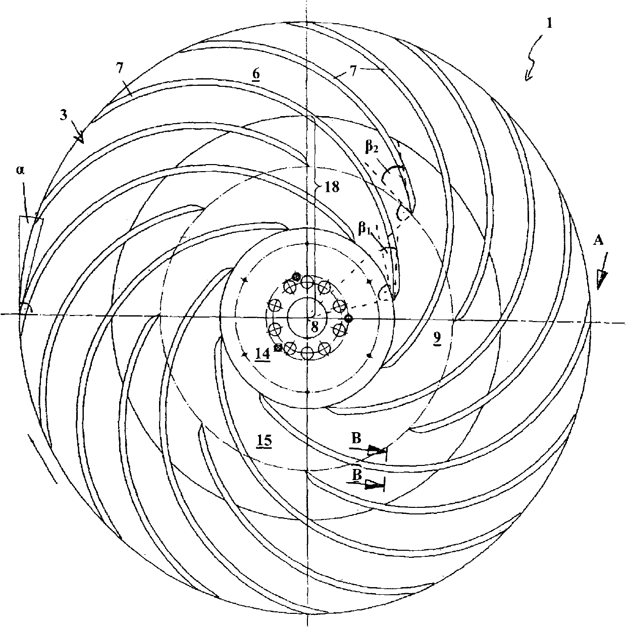
[0047] exist figure 1 A particularly efficient and advantageous rotor disk 1 is exemplarily shown in , wherein figure 1 The rotor disk 1 is shown viewed from below, ie from the storage base 17 during operation. In practice, such a rotor disk 1 is usually inserted into a large-volume holding store 2 in which a lot of polymer material with a correspondingly high weight is present. A correspondingly high pressure acts on the rotor disk 1 . In this case, the diameter of such a rotor disk 1 is in the range of approximately 2 m or more.

[0048] The rotor disk 1 has a disk body 3 on which mixing and / or grinding tools 5 can be arranged on an upper side 4 . A number of conveying ribs 7 extending from the inside to the outside are arranged on the opposite underside 6 of the tray body 3 . All conveying ribs 7 are curved concavely in the direction of travel of the disk 1 , wherein the curvature runs uniformly in the shape of a circular arc. The radius of curvature of the conveying r...


PUM


Abstract

The invention relates to a rotor disk (1) for inserting into a receiving container (2) for treating polymers, comprising a disk body (3), on the upper face (4) of which mixing and / or comminuting tools (5) can be provided and on the opposite lower face (6) of which a number of conveying ribs (7) extending from the inside out is provided, by means of which conveying ribs polymer particles can be conveyed outward during operation or which conveying ribs exert a force directed outward from the center (8) of the rotor disk (1) on the polymer particles caught by the conveying ribs (7) during operation. According to the invention, the thickness of the disk body (3) is reduced toward the outside.

Description

technical field [0001] The invention relates to a rotor disk according to the preamble of claim 1 Background technique [0002] Such rotor disks are known in several designs from the prior art. They are usually arranged close to the bottom of a holding store (Aufnahmebehaelter) or a cutting baler (Schneidverdichter) for the processing and preparation of thermoplastic polymers and essentially consist of a disc-shaped tool holder composition, a mixing and / or stirring tool or grinding tool (Zerkleinerungsmesser) is arranged on the upper side of the tool holder. During operation, the disk rotates and while heating, the tool captures and optionally grinds the plastic material placed in the store. In addition, the material is thoroughly stirred and continuously displaced, so that a mixing vortex is formed in the accumulator. [0003] Devices for processing polymers are basically also known from the prior art, for example from documents AT 375867B, AT 407970B or WO 93 / 18902. ...

Claims


Application Information

Patent Timeline
Patent Type & Authority Applications(China)
IPC IPC(8): B01F7/00B01F13/10B29B13/10B02C18/12B29B17/04B01F27/93
CPCB29B17/0412B02C18/18B02C18/086B29B2017/048B02C18/12Y02W30/62B01F27/00B01F33/80B29B13/10B02C18/182
Inventor M·哈克尔K·费希廷格G·温德林
Owner EREMA ENG RECYCLING MASCH & ANLAGEN GMBH
Learn More