Light source device and display device

A technology for a light source device and a display unit, which is applied to light sources, electric light sources, point light sources, etc., can solve problems such as inability to insert a screwdriver, and difficulty in releasing the fixing between a support body and a circuit substrate, and achieve the effect of preventing stress.

Inactive Publication Date: 2012-05-02
SHARP KK
View PDF11 Cites 4 Cited by
  • Summary
  • Abstract
  • Description
  • Claims
  • Application Information

AI Technical Summary

Problems solved by technology

[0033] In addition, in the LED-type backlight device, it is assumed that the circuit board is fixed to the support body using the rivet technology described in Patent Document 4. In this case, since only one part of the rivet is provided with a screwdriver etc. tools to release the fixation between the support body and the circuit board, therefore, there may be a problem that other objects such as lenses may become obstacles to the position of the notch when fixing the circuit board to the support body objects, so that tools such as screwdrivers cannot be inserted, and it is difficult to release the fixation between the support body and the circuit board

Method used


Image

  • Light source device and display device
  • Light source device and display device
  • Light source device and display device

Examples


Embodiment approach 1-1

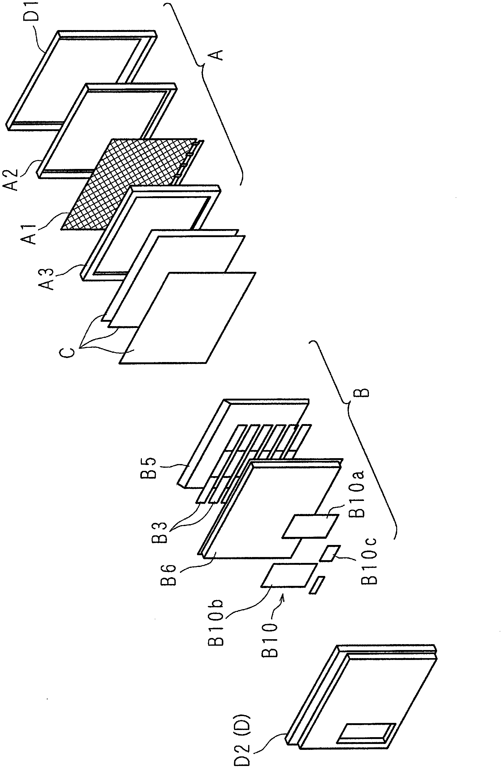
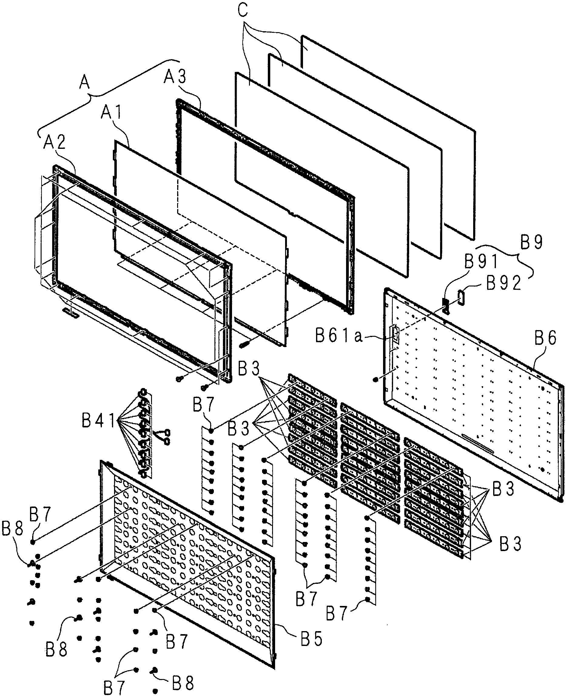
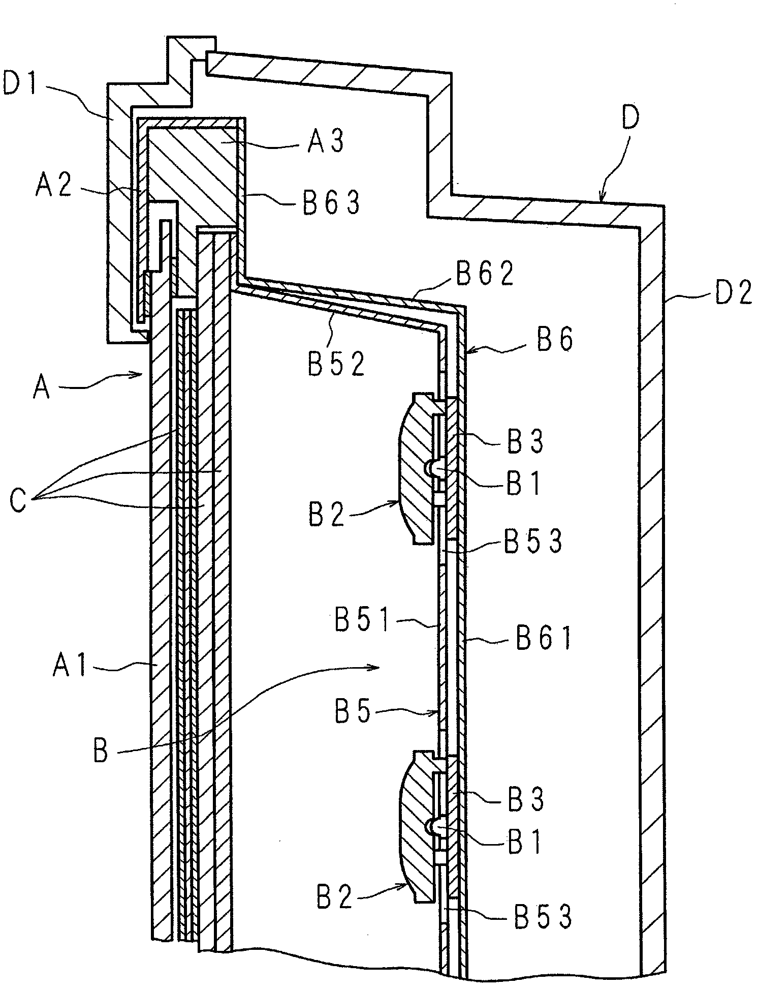
[0315] Figure 29 It is a perspective view showing the structure of the light source device according to the present invention, Figure 30 is a plan view showing the structure of the light source device, Figure 31 It is a plan view showing the structure obtained by omitting the reflection sheet of the light source device, Figure 32 It is an enlarged cross-sectional view showing a part of the structure of the light source device.

[0316] The illustrated light source device (B) is installed on the rear side of the display unit in the thin display device provided with the display unit (A). (B) includes: a plurality of light emitting diodes 1 (B1), which are arranged side by side in a grid shape as light sources; a plurality of light emitting diode substrates 2 (B3), and the plurality of light emitting diode substrates 2 (B3) arranged side by side in multiple rows, the light emitting diode 1 is installed on one surface 2a; a plurality of connectors 3 (B4), the plurality of c...

Embodiment approach 1-2

[0337] Figure 38 It is a developed front view showing another configuration of the main part of the reflection sheet included in the light source device according to the present invention. This light source device adopts the following structure: that is, a substantially V-shaped cutout portion 57 is provided at the corner 52a of the frame portion 52 instead of providing three second strips at the corner of the frame portion 52 of the reflection sheet 5 (B5). The folding line 53 bends the four frame parts 52 connected to the four sides of the flat part 51 obliquely with respect to the flat part 51 at the first folding line 5b, and the two edge parts 57a, 57a of the cutout part 57 Together, and utilize double-sided adhesive tape 55 to keep this combined state.

[0338] The reflection sheet 5 formed of a rectangular synthetic resin sheet material has a flat portion 51 smaller than the plate portion 61 of the supporting case 6, and four sides of the flat portion 51 connected at ...

Embodiment approach 1 1

[0341] Figure 39 It is a developed front view showing another structure of the main part of the reflection sheet included in the light source device according to the present invention, Figure 40 It is an enlarged front view showing other structures of the main part of the reflective sheet. This light source device adopts the following structure: that is, three second folding lines 53 extending from the corners 51a of the flat portion 51 of the reflective sheet 5 to the periphery of the frame body portion 52 and one cutout 58 are provided instead of the corners 51a of the flat portion 51 of the reflective sheet 5. The corner 52a of the frame part 52 is provided with a cutout 57, the corner 52a of the frame part 52 is formed by the second folding line 53, and the end parts of the adjacent frame parts 52 are combined with each other by a cutout 58. The double-sided tape maintains the closed state and the corners 52a.

[0342] The cutouts 58 are arranged to extend from the cor...


PUM


Abstract

Disclosed are a light source device and a display device capable of preventing stress from occurring in, for example, connectors and a plurality of circuit boards connected by the connectors when the circuit boards are fixed to a supporting body using fasteners. Specifically disclosed is a light source device which comprises a plurality of circuit boards (2) each having light-emitting elements (1) that are mounted on a first surface (2a) thereof and being disposed so as to be remote from each other such that the surfaces thereof are parallel to each other, a supporting body (6) disposed on second surfaces of the plurality of circuit boards (2) so as to support the circuit boards, and connectors (5) electrically connecting two adjacent circuit boards (2). A plurality of insertion holes (2c, 2d) into which fasteners (8) for fixing the circuit boards (2) to the supporting body (6) are fitted are formed in each circuit board (2) so as to be remote from each other. The size of the insertion hole (2c) among the plurality of insertion holes (2c, 2d) is smaller than that of the insertion hole (2d).

Description

technical field [0001] The present invention relates to a light source device provided with a light emitting element, and a display device provided with the light source device. Background technique [0002] A so-called thin liquid crystal display device such as a liquid crystal television includes a substantially rectangular parallelepiped display unit having a display surface on which an image is displayed on the front side, and a light source device arranged on the back side of the display unit to irradiate light to the display unit. Optical sheets such as a diffusion plate and a prism sheet are disposed between the device and the display unit. [0003] The display unit has a substantially rectangular parallelepiped liquid crystal display panel. Since the liquid crystal display panel itself cannot emit light, it needs an illumination source for displaying video on the display surface, and a backlight device is used as the illumination source. [0004] The backlight devi...

Claims


Application Information

Patent Timeline
Patent Type & Authority Applications(China)
IPC IPC(8): F21S2/00F21V7/00F21V7/10G02B5/08G02F1/13357F21Y101/02
Inventor 竹内秀仁藤田稔之菅原达夫川村优贵谷畑守高桥洋伊藤启太岁行健藏伊东贤一郎中道一喜佐佐木智雄守部研太
Owner SHARP KK
Why Eureka
Try Eureka