Pressure sensor and method of adjusting the same

A technology of pressure sensor and adjustment method, which is applied in the direction of converting sensor output, measuring fluid pressure, measuring fluid pressure through electromagnetic components, etc., to achieve the effect of simple range adjustment method, cost reduction, and size reduction

Inactive Publication Date: 2012-05-02
SAGINOMIYA SEISAKUSHO INC
View PDF11 Cites 12 Cited by
  • Summary
  • Abstract
  • Description
  • Claims
  • Application Information

AI Technical Summary

Problems solved by technology

In addition, since two expensive magnets (rare earth neodymium, cobalt samarium (CoSm), etc.) are used, there is a problem in terms of cost

Method used


Image

  • Pressure sensor and method of adjusting the same
  • Pressure sensor and method of adjusting the same
  • Pressure sensor and method of adjusting the same

Examples


Embodiment Construction

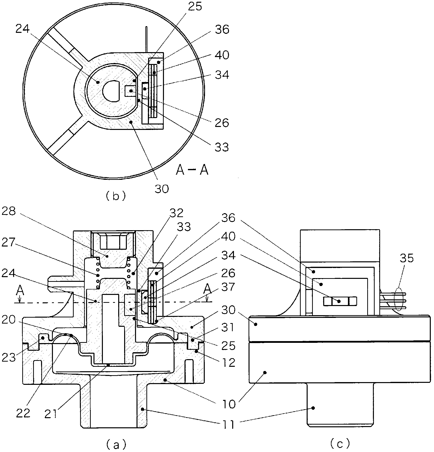
[0047] figure 1 It is a figure which shows the structure of the 1st Embodiment of the pressure sensor of this invention, (a) is a cross-sectional view of the pressure sensor of this embodiment, (b) is A-A line cross-sectional view of (a), (c) is a side view. Furthermore, the pressure sensor of the present invention is used, for example, as a micro-pressure sensor for a rice cooker.

[0048] In this figure, 10 is a joint body, 20 is a diaphragm, and 30 is an upper body. At the center of the bottom surface of the joint body 10 is provided a joint portion 11 having an inlet for introducing a fluid to be measured, and a stepped portion 12 is formed on the upper surface of the joint body 10 . The above-mentioned diaphragm 20 is made of, for example, high-hardness silicone rubber, and a pressure-receiving plate support portion 21 is formed at the center, and a ring-shaped thick-walled elastic force applying portion 22 is formed around it, and a flange portion is formed on the perip...


PUM

PropertyMeasurementUnit
porosityaaaaaaaaaa

Abstract

Provided is a pressure sensor wherein sensitivity can be adjusted by a simple structure. The peripheral portion of a diaphragm (20) is held between a joint body (10) and an upper body (30). A pressure receiving plate (24) provided with a permanent magnet (26) is installed on the diaphragm (20) and detects the displacement of the aforementioned permanent magnet (26), that is, the displacement of the diaphragm (20), by means of a linear Hall IC (34) installed in the aforementioned upper body (30). A plate (40) comprising a steel sheet provided with a square hole is installed on the outside of the linear Hall IC (34). By selecting a plate comprising a steel sheet located in a different position or a plate provided with a square hole having a different longitudinal dimension, or by removing the plate, adjustments are made so that the pressure sensor accuracy meets the accuracy requirement.

Description

technical field [0001] The present invention relates to a pressure sensor that uses a Hall element to detect the displacement of a diaphragm that follows the pressure of a fluid and an adjustment method thereof. Background technique [0002] When detecting the pressure of the fluid, the pressure of the fluid is introduced to one surface of the diaphragm, and the force of the fluid that moves the diaphragm against the elastic force applied to the other surface of the diaphragm is detected as the pressure. A product that operates a mechanical switch through a diaphragm displaced by fluid pressure to output a predetermined pressure as a signal, and a product that outputs an analog output signal corresponding to the displacement of the diaphragm are known. [0003] Piezoresistive (semiconductor) pressure sensors and capacitive pressure sensors are known as products that output a signal having a magnitude corresponding to the displacement of the diaphragm, but both are expensive....

Claims


Application Information

Patent Timeline
Patent Type & Authority Applications(China)
IPC IPC(8): G01L9/14G01B7/00G01D5/14G01R33/07
CPCG01L9/14G01L9/007G01D5/145
Inventor 樱井明金井佑二
Owner SAGINOMIYA SEISAKUSHO INC
Why Eureka
Try Eureka