Safety monitoring device

A monitoring device and safety technology, applied in the fields of medical science, diagnosis, diagnostic recording/measurement, etc., can solve problems such as undetectable changes in breathing, undetectable changes in breathing acceleration, cessation, undetectable changes in health status, etc. To achieve the effect of preventing false detection

Inactive Publication Date: 2012-05-09
KONICA MINOLTA INC
View PDF12 Cites 15 Cited by
  • Summary
  • Abstract
  • Description
  • Claims
  • Application Information

AI Technical Summary

Problems solved by technology

[0013] The prior art shown in Patent Document 1 can detect if the person in the residence is in a moving state, but cannot detect the change in appearance and the state of health of the person when there is little movement of the person.
That is, the infrared rays produced by the people can be detected by the infrared sensors 201a-201c arranged in each room and the activities of the people can be deduced by analogy. When there is less activity such as watching TV or reading a book, it is impossible to detect the deterioration of appearance and the deterioration of appearance during sleep
In addition, since the infrared sensor is used, it is impossible to

Method used


Image

  • Safety monitoring device
  • Safety monitoring device
  • Safety monitoring device

Examples


Embodiment 1

[0144] Below, refer to Figure 1 to Figure 9 Embodiment 1 of the safety monitoring device of the present invention will be described in detail.

[0145] (principle description of the present invention: Figure 8 , Figure 9 )

[0146] First, use Figure 8 and Figure 9 The principle of signal detection by a microwave Doppler sensor mounted on a safety monitoring device will be described. Figure 8 is a schematic diagram showing a microwave Doppler sensor and a subject. Figure 9 It is a waveform diagram for explaining the signal waveform detected by the microwave Doppler sensor.

[0147] Figure 8 Among them, 31 is a microwave transmitter, 32 is a microwave receiver, and 33 is a microwave demodulator. The microwave Doppler sensor 3 is composed of them. 10 is a test subject, and 10a is a respiratory muscle. The respiratory muscles 10a are a general term for muscles that expand and contract the thorax during respiration. For example, with diaphragm, internal intercost...

Embodiment 2

[0253] (Structure description of safety monitoring device: Figure 10 )

[0254] Next, use Figure 10 Embodiment 2 of the safety monitoring device will be described. In the safety reporting device 7 of the safety monitoring device 100 related to Embodiment 2, a communication monitoring part 73a for monitoring the function of the communication part 73 is also added, so that the safety monitoring operation is reliable. Sex is higher.

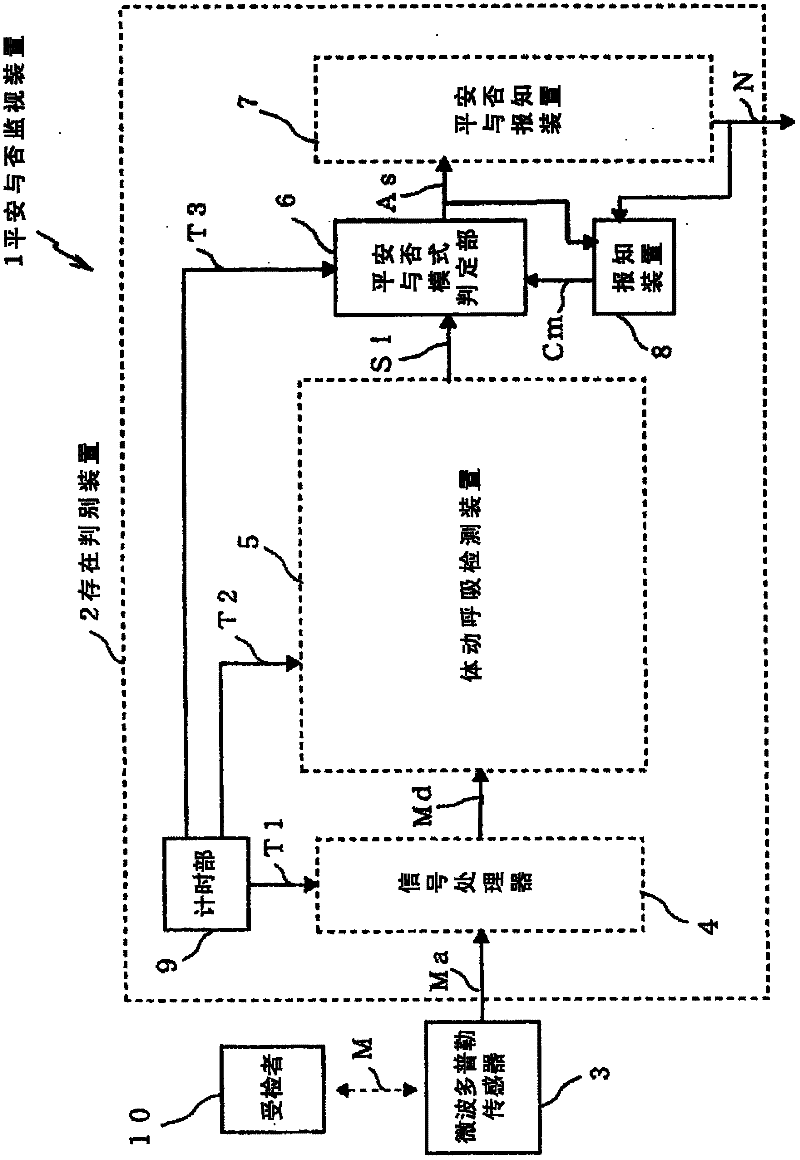
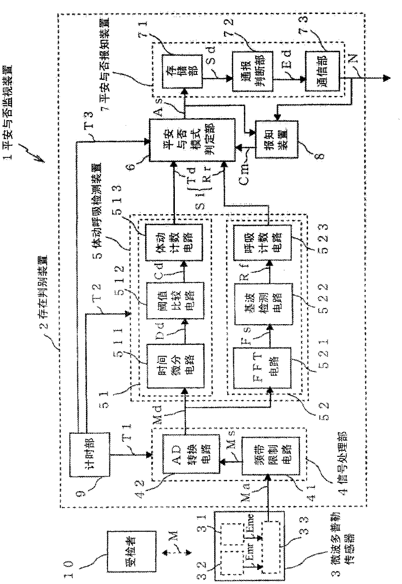
[0255] Figure 10 It is a functional block diagram showing the configuration of the safety monitoring device 100, and only shows the safety notification device 7a and the related notification device 8, which are requirements different from the first embodiment.

[0256] The communication monitoring part 73a of the safety notification device 7a outputs a function check signal Hk to the communication part 73, and judges whether the function of the communication part 73 is normal. Specifically, the function check signal Hk is a test program for ...

Embodiment 3

[0262] (Structure divided into sensor unit and server)

[0263] The security monitoring device 1,100 of each of the above-mentioned embodiments can form the following structure: as Figure 12 Shown, microwave Doppler sensor 3, signal processing part 4, timing part 9 and body movement respiration detection device 5 are constituted as an integrated sensor unit 300, safe or not mode judging part 6, safe or not reporting device 7 and reporting device. Knowing device 8 is provided in server 400 which is separate from sensor unit 300 and is integrated, and sensor unit 300 and server 400 are connected via communication line 600 .

[0264] Furthermore, the sensor unit 300 is installed in a specific space such as a room where the subject 10 who is the subject of monitoring by the safety monitoring apparatus 1 and 100 usually resides, for example.

[0265] On the other hand, the server 400 is installed in a place different from the installation place of the sensor unit 300 (a place whe...


PUM


Abstract

The present invention provides a safety monitoring device which is provided with a microwave doppler sensor. A microwave doppler frequency shift signal which is output from the microwave doppler sensor is used for calculating the number of body motions and number of breaths. Whether an examined person is safe is monitored according to a combined safe mode above the number of body motions and the number of breaths. Therefore, not only can safe be determined without body movement, but also the state of the examined person can be detected, thereby overcoming the defects in the prior-art safety monitoring device, such as incapability of determining safety at the state of long-time TV watching without large body movement, incapability of detecting abnormity in the healthy state, etc.

Description

technical field [0001] The present invention relates to a safety monitoring device which detects the daily living conditions and abnormalities in the health status of people living alone such as elderly people living alone, and monitors the overall physical status. Background technique [0002] In recent years, the social structure has become more complicated, and the number of people living alone has increased, such as those who are single or students who live alone in a place convenient to school. In addition, as society ages, so-called elderly people living alone are also increasing. The so-called elderly living alone refers to the elderly who have to live alone for some reason. [0003] If you are a relatively young student or a single person, you have more opportunities to contact others when you go to school, go to work, or on the way to school or work, while elderly people living alone have few reasons such as lack of contact within the family. A person who does not...

Claims


Application Information

Patent Timeline
IPC IPC(8): A61B5/08A61B5/11
Inventor 清水秀树
Owner KONICA MINOLTA INC
Why Eureka
Try Eureka