U-shaped force-bearing seat and construction method of steel beam-reinforced concrete floor slab structure

A technology of reinforced concrete and bearing seat, which is applied in the on-site preparation of building components, connection of formwork/formwork/work frame, building structure, etc., can solve the problems of waste of resources, high cost and high cost, and achieve Low amortized cost and the effect of reducing labor intensity

Inactive Publication Date: 2012-05-09
潘克远
View PDF5 Cites 6 Cited by
  • Summary
  • Abstract
  • Description
  • Claims
  • Application Information

AI Technical Summary

Problems solved by technology

The galvanized steel plate in this kind of combined formwork is mainly stressed during the construction stage, and generally no longer participates in bearing the load during the normal use period of the building, which causes a waste of resources; the steel bars in the combined formwork are designed to be used as reinforced concrete in an equivalent substitution method The stressed steel bars in the floor are not wasted, but the cost of factory processing is higher
On the whole, the cost of this combination template is relatively high, which is its shortcoming

Method used


Image

  • U-shaped force-bearing seat and construction method of steel beam-reinforced concrete floor slab structure
  • U-shaped force-bearing seat and construction method of steel beam-reinforced concrete floor slab structure
  • U-shaped force-bearing seat and construction method of steel beam-reinforced concrete floor slab structure

Examples


Embodiment Construction

[0034] The present invention will be further described below in conjunction with the accompanying drawings and specific embodiments.

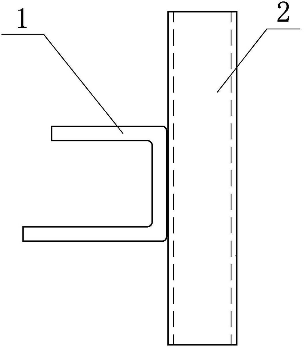
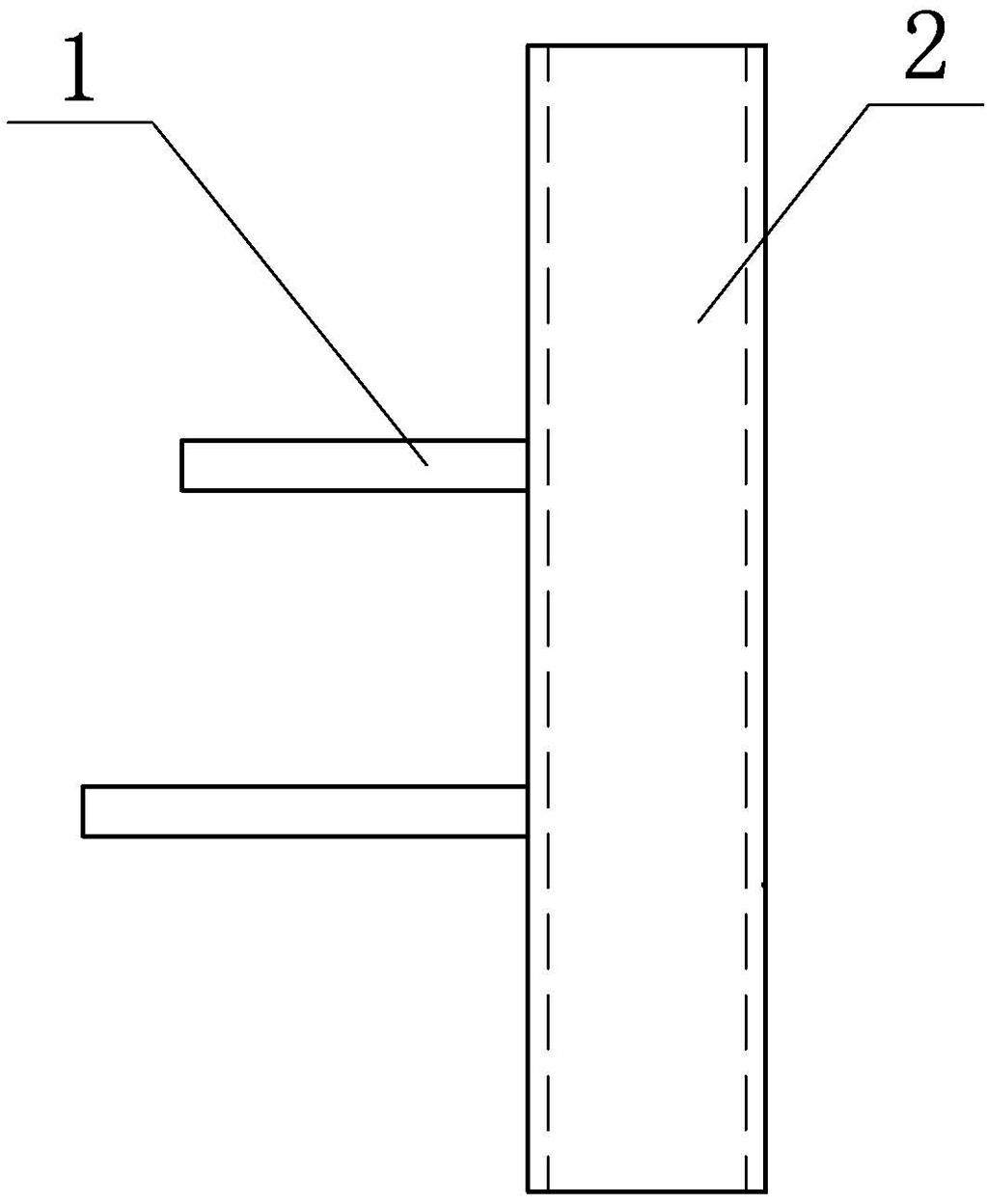
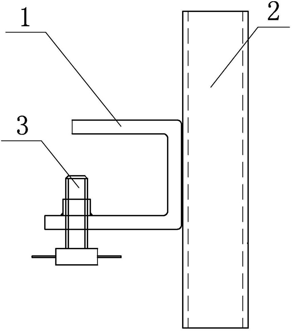
[0035] like Figure 1-8 As shown, a U-shaped load-bearing seat includes a U-shaped load-bearing member 1 and a socket part 2 fixed on the U-shaped load-bearing member. The socket part 2 can be a socket steel pipe, a socket screw or a square steel pipe The U-shaped bearing seat can also include a jacking bolt 3 arranged on the U-shaped bearing member 1, preferably 1 or 2 jacking bolts 3, and can also include a jacking bolt 3 arranged on the socket part 2 Tighten the bolts, or fix the tension bolts 4 on the auxiliary steel plate 10, and the auxiliary steel plate 10 is fixed on the socket part 2 or the U-shaped load-bearing member 1. like figure 2 As shown, the U-shaped load-bearing member 1 can also be composed of two rods fixed on the socket part 2 and the part of the socket part 2 between the two rods. The schematic diagram of the above-men...


PUM


Abstract

The invention discloses a U-shaped force-bearing seat, which is characterized by comprising a socket joint part and a U-shaped force-bearing member, wherein the bottom of a U-shaped groove of the U-shaped force-bearing member is fixed on the socket joint part, the U-shaped force-bearing seat further comprises a puller bolt arranged on the U-shaped force-bearing member and a tightening bolt arranged on the socket joint part or the tightening bolt is fixedly arranged on an auxiliary steel plate, and the auxiliary steel plate is fixed on the socket joint part or the U-shaped force-bearing member. The invention further discloses a construction method of a steel beam-reinforced concrete floor slab structure. Compared with the traditional support formwork manner, the construction method disclosed by the invention can reduce a large number of vertical force-bearing rod parts and horizontal connecting rods for stabilizing the vertical force-bearing rods and greatly reduce the labor intensity of field workers; compared with a steel bar truss-galvanized steel sheet combined formwork, the labor intensity of the field workers is greater; and if the construction method is matched with special mechanical equipment, the construction speed of the construction method can achieve the construction speed of the steel bar truss combined formwork and meet the requirements on construction progress of a main body of an ultra-high-rise project.

Description

technical field [0001] The invention relates to the field of construction engineering, in particular to a construction method of a U-shaped bearing seat for supporting formwork and a steel beam-reinforced concrete floor structure. Background technique [0002] With the shortage of urban land, there are more and more super high-rise buildings with the structure of "concrete steel tube column-steel beam-concrete core tube". The hoisting construction of concrete columns and steel beams can also be controlled at an average speed of no more than 3 days per floor, and the formwork support of the cast-in-place reinforced concrete floor slabs that form the permanent horizontal load-bearing structure of the building together with the steel beams has become a must. issues to be resolved. [0003] At present, there are two solutions: (1) Traditional formwork method: this method is to support the formwork support frame on the reinforced concrete floor slab that has been constructed...

Claims


Application Information

Patent Timeline
Patent Type & Authority Applications(China)
IPC IPC(8): E04G17/00E04G21/02
Inventor 潘克远
Owner 潘克远
Why Eureka
Try Eureka