
Semiconductor cooling device

A heat dissipation device and semiconductor technology, applied in the direction of semiconductor devices, semiconductor/solid-state device parts, electric solid-state devices, etc., can solve the problems of poor heat dissipation effect, achieve good heat dissipation effect, high work efficiency, and convenient use

Inactive Publication Date: 2012-05-09
OCEANS KING LIGHTING SCI&TECH CO LTD +1
View PDF3 Cites 7 Cited by
  • Summary
  • Abstract
  • Description
  • Claims
  • Application Information

AI Technical Summary

Problems solved by technology

[0006] The purpose of the embodiments of the present invention is to provide a semiconductor heat sink, aiming to solve the problem of poor heat dissipation in existing semiconductor heat sinks

Method used


Image

  • Semiconductor cooling device
  • Semiconductor cooling device

Examples


Embodiment Construction

[0014] In order to make the object, technical solution and advantages of the present invention clearer, the present invention will be further described in detail below in conjunction with the accompanying drawings and embodiments. It should be understood that the specific embodiments described here are only used to explain the present invention, not to limit the present invention.

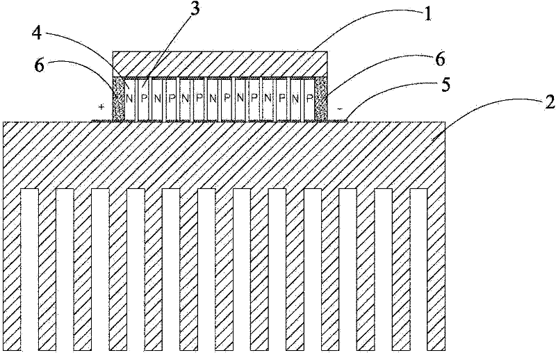
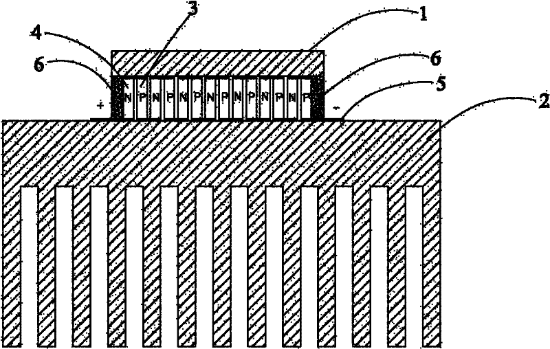
[0015] figure 1 The structure of the semiconductor heat sink provided by the embodiment of the present invention is shown, and for the convenience of description, only the parts related to the present invention are shown.

[0016] The semiconductor cooling device includes a cold end 1, a hot end 2, and several pairs of P-type semiconductors 3 and N-type semiconductors 4 between the cold end 1 and the hot end 2, and several pairs of P-type semiconductors 3 and N-type semiconductors 4 are arranged alternately. Each pair of P-type semiconductors 3 and N-type semiconductors 4 are connected head to tai...


PUM


Abstract

The invention is suitable for the technical field of heat dissipation, and provides a semiconductor cooling device. In the invention, compared with the traditional passive heat dissipation manners such as a fan, a cooling fin, a heat pipe and the like for cooling an exothermic electronic component, the semiconductor cooling device has the advantages that a semiconductor material with a thermoelectric energy conversion characteristic is utilized, so that the semiconductor cooling device has a refrigeration function when powered on so as to initiatively and rapidly absorb a great deal of heat generated by the exothermic electronic component in the work; and meanwhile, ceramic adopted at the hot end of the semiconductor cooling device is provided with cooling fins, so that the heat dissipation area is enlarged, therefore, the heat dissipation effect is better, and the cooling device has no noises and no mechanical part and is more convenient in use, thus the work efficiency of the electronic component is higher, and the service life of the electronic component is longer.

Description

technical field [0001] The invention belongs to the technical field of heat dissipation, and in particular relates to a semiconductor heat dissipation device. Background technique [0002] Integrated circuit chips, light-emitting diodes, etc. are electronic components with high heat generation. Due to the concentrated heat, if the heat dissipation is not handled properly, these electronic components may not work normally or even burn out. [0003] At present, the heat dissipation measures for these electronic components mainly use heat sinks, or heat sinks and fans. The simple use of heat sinks has many disadvantages: first, it requires a large area and a large space; second, heat backflow. For the method of adding a fan to assist heat dissipation, including many mechanical parts used to drive the fan, any failure of any of these parts may cause the fan to not work properly, which will obviously cause improper cooling; The air in the air contains moisture and dust, which wi...

Claims


Application Information

Patent Timeline
IPC IPC(8): H01L23/38H01L23/367F25B21/02
Inventor 周明杰马文波陈贵堂
Owner OCEANS KING LIGHTING SCI&TECH CO LTD
Learn More