Method for supplying refined liquefied gas

A liquefied gas and gas phase technology, applied in refrigeration and liquefaction, container discharge methods, liquefaction, etc., can solve problems such as the increase of non-volatile impurities and the reduction of the remaining amount of liquefied gas

Inactive Publication Date: 2012-05-09
NIPPON SANSO CORP
View PDF4 Cites 4 Cited by
  • Summary
  • Abstract
  • Description
  • Claims
  • Application Information

AI Technical Summary

Problems solved by technology

[0005] When supplying liquefied gas in a gaseous state (gaseous state), the following problems will inevitably arise in principle: volatile impurities that are more present in the gas phase at the beginning of use from the container (oxygen and methane gas in the case of liquefied ammonia) etc.) is supplied together with the gas, and due to the supply of liquefied gas, the remaining amount of liquefied gas in the container decreases, so less volatile impurities (water in the case of liquefied ammonia) are concentrated in the liquid phase, and as a result, the supplied Increased low-volatile impurities in the gas

Method used


Image

  • Method for supplying refined liquefied gas
  • Method for supplying refined liquefied gas
  • Method for supplying refined liquefied gas

Examples


Embodiment 1

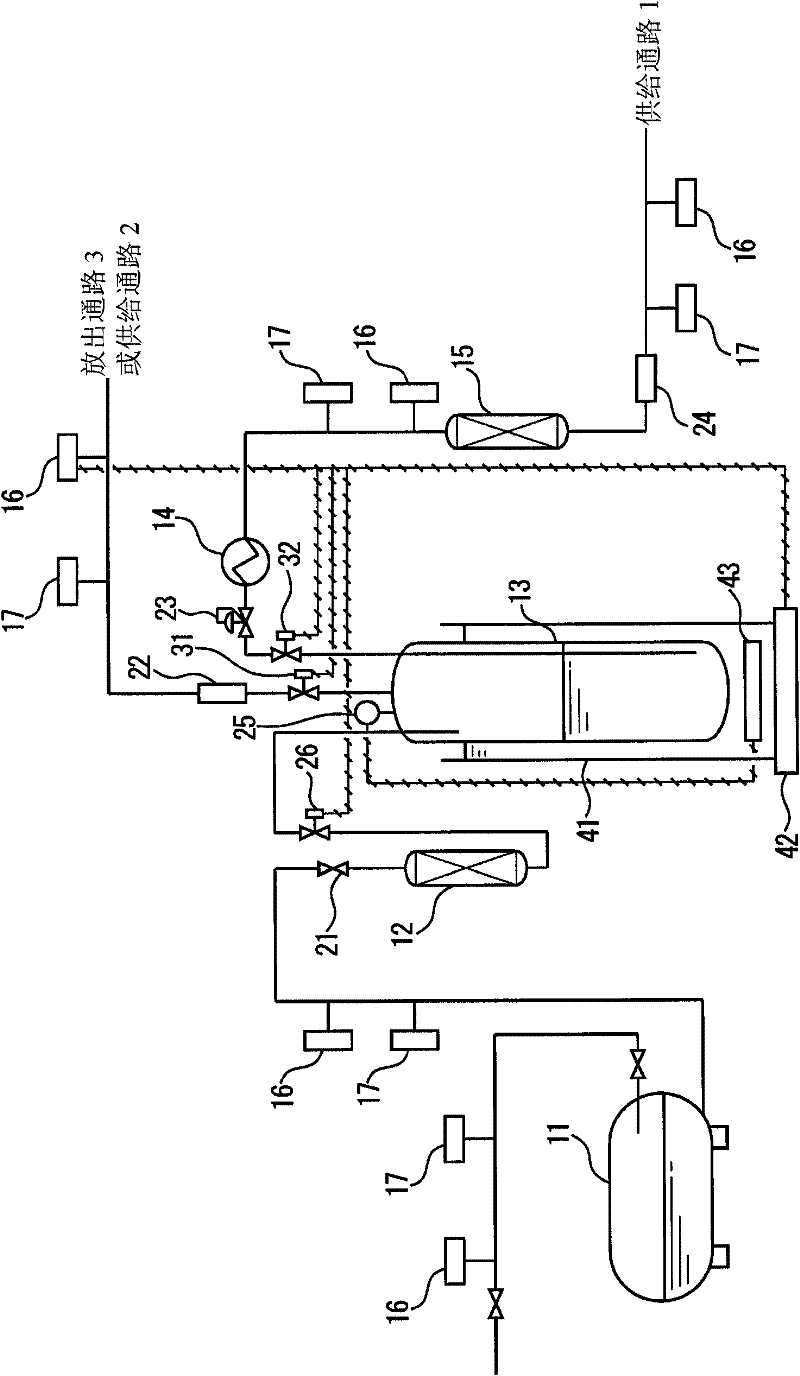
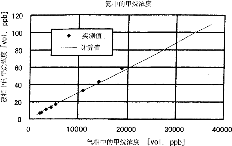
[0315] In Example 1, the use of figure 1 The above-mentioned purification tank (13) of the type shown in the flow chart of the above-mentioned purification of the raw material liquefied ammonia Figure 5 The relationship between the amount of outgassing gas and the reduction in gas phase impurity concentration and liquid phase impurity concentration is shown.

[0316] The concentration of impurity methane contained in the gas phase component in the refining tank (13) was measured by a gas chromatograph GC-PDD (manufactured by GL Science, type: gas chromatograph with a pulse discharge detector), and the concentration of the impurity methane contained in the liquid phase component The concentration of impurity methane in the sample was collected from the liquid phase, the sample was vaporized and homogenized with a vaporizer, and measured with the above-mentioned gas chromatograph.

[0317] (1) Refining device

[0318] The inner volume of the refining tank (13) was 20 liters (...

Embodiment 2

[0338] The liquefied ammonia of the same volatile impurity concentration in the liquefied ammonia was transferred and filled into the refining tank as the raw material liquefied ammonia used in Example 1, and the gas was released from the gas phase part, thereby refining the liquefied ammonia.

[0339] (1) Refining device

[0340] The inner volume of the refining tank (13) was 20 liters (inner diameter 220 mm, height 525 mm).

[0341] The refining apparatus used the same apparatus as that used in Example 1.

[0342] like figure 1 As shown, the storage vessel (11) is connected to the refining tank (13) via the oil removal device (12) through piping in a form that can be filled with liquefied gas, and the discharge passage 3 is connected to the gas phase for measuring the concentration of impurities contained in the gas phase components. A chromatograph (16) is connected, the supply passage 1 is connected to a water removal cartridge (15) filled with an adsorbent capable of re...

Embodiment 3

[0360] The liquefied ammonia of the same volatile impurity concentration in the liquefied ammonia was transferred and filled into the refining tank as the raw material liquefied ammonia used in Example 1, and the gas was released from the gas phase part, thereby refining the liquefied ammonia.

[0361] (1) Refining device

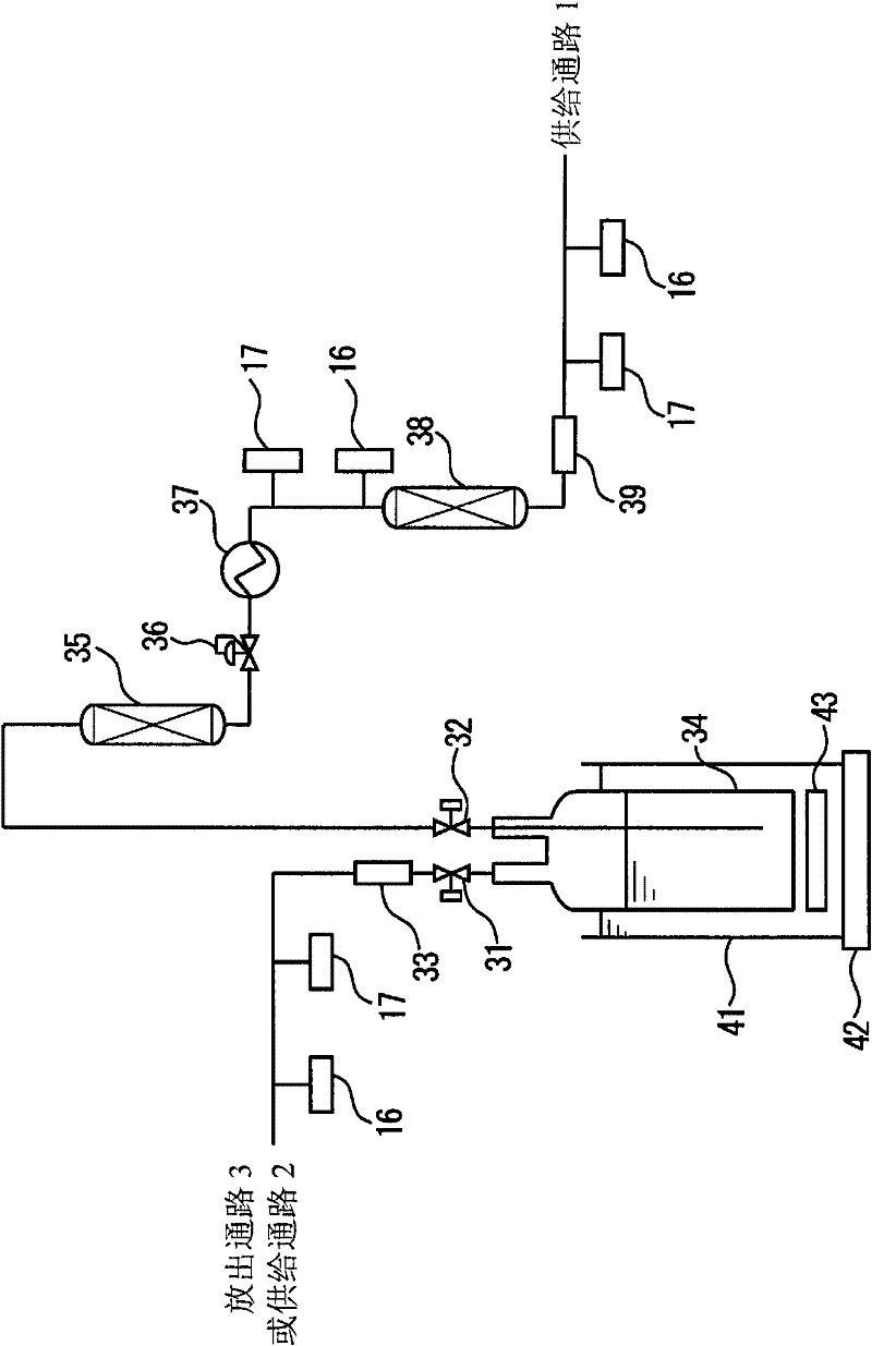
[0362] As a refining device, use figure 2 Siphon type refining tank (34) shown (inner volume: 100 liters, inner diameter: 350 mm, height: 1000 mm).

[0363] In the purification tank ( 34 ), 50 kg of liquefied ammonia, a raw material that is substantially the same as that used in Example 1, was stored in a state maintained at 25° C. and 0.898 MPa.

[0364] The refining tank (34) passes through an oil removal device (35), a pressure reducing valve (36), a vaporizer (37) from a liquid phase extraction valve (32), and a water removal cylinder (38) filled with an adsorbent capable of removing water. )connect. In addition, a CRDS-type moisture meter (17) is c...


PUM


Abstract

A method for supplying a refined liquefied gas, in which prior to the supply of a liquefied gas stored in a container, the liquefied gas is refined by discharging the gas constituting a gas phase part within the storage container. The method for supplying a refined liquefied gas is characterized in that a raw liquefied gas in a refinement tank, the raw liquefied gas containing highly volatile impurities, is refined by implementing the following operations and is then supplied to a receiver. (1) An operation in which the concentrations of the impurities in the gas phase are determined, then the concentration of each impurity in the liquid phase is estimated from the ratio between the liquid-phase concentration and the gas-phase concentration of the impurity (gas-liquid equilibrium constant (Kn)), and the amount of the gas to be discharged from the gas phase part within the refinement tank in order to refine the liquefied gas is assumed, (2) an operation in which the gas is discharged from the gas phase part to thereby refine the liquefied gas constituting the liquid phase, (3) an operation in which after completion of the discharge, the gas phase is sampled and the quality of the refined liquefied gas is ascertained, and (4) an operation in which after the quality of the refined liquefied gas is ascertained, the refined liquefied gas is supplied to a receiver from the refinement tank.

Description

technical field [0001] The present invention relates to a method for supplying a purified liquefied gas, comprising purifying a raw material liquefied gas containing one or more impurity components that are more volatile than the liquefied gas as a main component stored in a purification tank, The purified liquefied gas is supplied to the supply target. Background technique [0002] As a liquefied gas commonly used in semiconductor manufacturing processes and the like, for example, a high purity of 99.999 (vol%) or more is required. Conventionally, in the purification for high-purity liquefied gas, the following purification operations are performed. Gas manufacturing plants use multi-stage rectification or various adsorbents to remove impurities. In addition, with the recent increase in the diameter of wafers and the increase in production volume, the amount of liquefied gas used has increased. As a result, for example, the ammonia liquefied gas container used in semicondu...

Claims


Application Information

Patent Timeline
Patent Type & Authority Applications(China)
IPC IPC(8): B01D3/42F17C9/00F25J3/02
CPCB01D3/42F17C2201/0109F17C2223/047F17C2250/0491F17C9/00F17C2225/0153F17C2223/046F17C2225/043F25J3/02F17C2223/043F17C2265/017F17C2201/035F17C5/00F17C2223/0153F17C2205/0323F17C2250/0452F17C7/00
Inventor 清水秀治有村忠信
Owner NIPPON SANSO CORP
Why Eureka
Try Eureka