Power flow control in a meshed HVDC power transmission network

A technology of DC current and power flow, applied in the direction of load balancing in DC network, power transmission AC network, conversion of AC power input to DC power output, etc., can solve the problem of no mesh HVDC network discussion and so on

Active Publication Date: 2012-05-09
HITACHI ENERGY SWITZERLAND AG
View PDF3 Cites 16 Cited by
  • Summary
  • Abstract
  • Description
  • Claims
  • Application Information

AI Technical Summary

Problems solved by technology

[0005] So far, the operation of meshed HVDC networks under fault-free operating conditions has not been discussed in the prior art

Method used


Image

  • Power flow control in a meshed HVDC power transmission network
  • Power flow control in a meshed HVDC power transmission network
  • Power flow control in a meshed HVDC power transmission network

Examples


Embodiment Construction

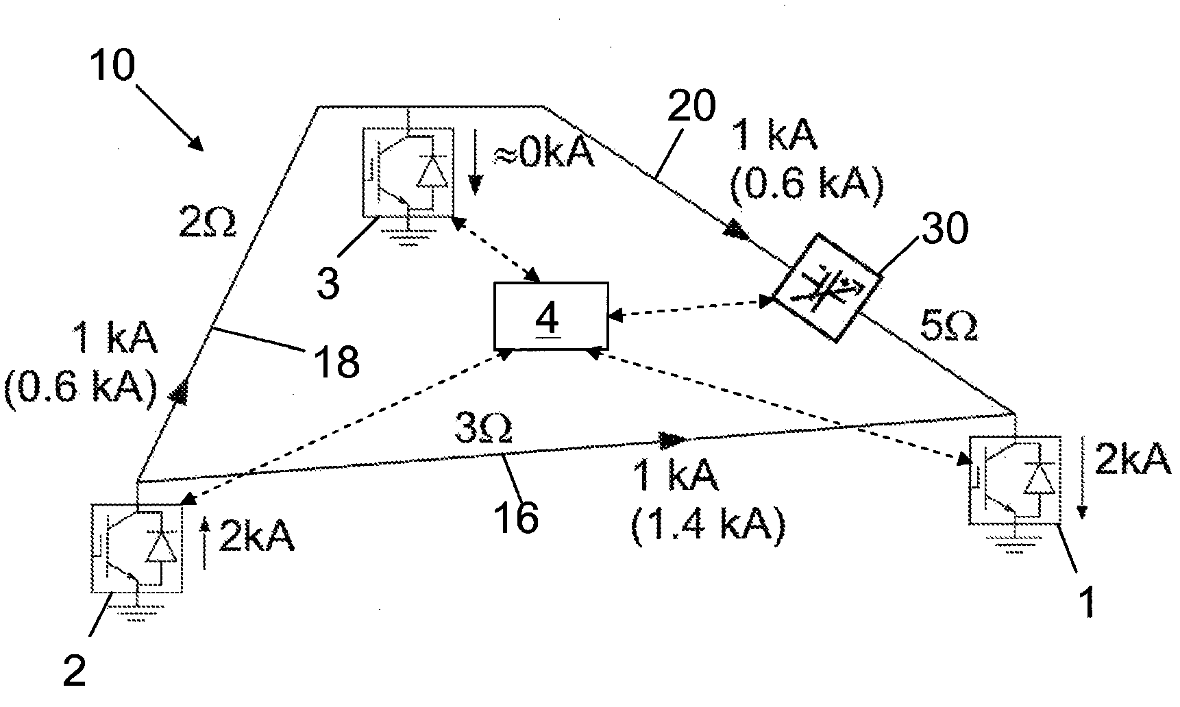
[0026] figure 1 A meshed HVDC transmission network 10 in the form of a closed path, also referred to as a first closed path, is shown, which connects three HVDC converter stations 1, 2 and 3 interconnections. The power flow is directly from converter station 2 to converter station 1 and converter station 3 and from converter station 3 to converter station 1 as indicated by the arrows for the current direction. Between the converter station 1 and the converter station 3, a DC power flow control device 30 is connected in series to the transmission line 20, the DC power flow control device 30 has the capability of adjusting the current distribution in the first closed path such that the current The distribution is balanced so as to avoid overcurrent in any of the three transmission lines. The DC power flow control device 30 directly receives the power of the DC power flow control device 30 itself from the transmission line 20 . The central control unit 4 controls the operation...


PUM


Abstract

A meshed HVDC power transmission network (10) comprises at least three HVDC converter stations (1, 2, 3) interconnected in a first closed path by at least three transmission lines (16, 18, 20). A first DC power flow control device (30) is series connected to a first (20) of the at least three transmission lines. That first DC power flow control device (30) takes its power from the first transmission line (20) and balances the DC current distribution in the first closed path.

Description

technical field [0001] The invention relates to a meshed HVDC transmission network comprising at least three HVDC converter stations interconnected in a first closed path by at least three transmission lines. The invention also relates to a method of controlling power flow in such a network and to a DC power flow control device arranged to be connected to one of the transmission lines in the network. Background technique [0002] In the prior art, it is generally known that HVDC power transmission is realized via double-ended HVDC links in a point-to-point interconnection manner. Such a double-ended HVDC link is an HVDC transmission system comprising two power conversion stations, one at each end of the transmission line. Transmission lines are usually unipolar lines or bipolar lines comprising a first pole at a high DC voltage of several hundred kilovolts up to thousands of kilovolts and a high pole connected to ground or to the opposite polarity, respectively. DC voltage...

Claims


Application Information

Patent Timeline
Patent Type & Authority Applications(China)
IPC IPC(8): H02J3/36H02M7/757H02H7/28H02H7/26
CPCY02E60/60H02J3/36H02H7/26H02J1/14H02J3/38H02M7/757
Inventor 拉尔斯-埃里克·尤林
Owner HITACHI ENERGY SWITZERLAND AG
Why Eureka
Try Eureka