
Computed tomography (CT) equipment and a scout view imaging method

A positioning image and equipment technology, applied in computerized tomography scanners, echo tomography, etc., can solve the problem of high cost of detectors and achieve the effect of reducing X-ray exposure dose

Inactive Publication Date: 2012-05-16
SIEMENS SHANGHAI MEDICAL EQUIP LTD
View PDF6 Cites 8 Cited by
  • Summary
  • Abstract
  • Description
  • Claims
  • Application Information

AI Technical Summary

Problems solved by technology

However, replacing a new detector requires a lot of cost

Method used


Image

  • Computed tomography (CT) equipment and a scout view imaging method
  • Computed tomography (CT) equipment and a scout view imaging method
  • Computed tomography (CT) equipment and a scout view imaging method

Examples


Embodiment Construction

[0038] In order to make the purpose, technical solution and advantages of the present invention clearer, the following examples are given to further describe the present invention in detail.

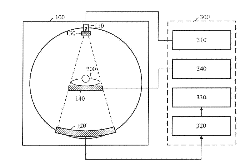
[0039] figure 2 A CT device according to an embodiment of the present invention is schematically presented. It should be noted that, for the purpose of brevity, other components in the CT equipment that are not closely related to the present invention are omitted in the drawings and the following description of the present invention.

[0040] Such as figure 2 As shown, the CT equipment includes a CT scanner (scanner) 100 and a control and image reconstruction system 300 . Wherein, the CT scanner 100 includes at least one X-ray tube 110 , a collimator 130 and a detector 120 corresponding to the X-ray tube, and also includes a hospital bed 140 .

[0041] The X-ray tube 110, the collimator 130 and the detector 120 are arranged in the rotating part of the CT scanner (not shown in the fi...


PUM


Abstract

The invention discloses computed tomography (CT) equipment, which comprises at least one X-ray tube (110), a detector (120), an image reconstruction device (330), an exposure control device (310) and a data supplementary device (320), wherein the detector (120) is used for receiving X rays from the X-ray tube to generate the original data; the image reconstruction device (330) is used for reconstructing an image based on the original data to acquire a scout view; the exposure control device (310) is used for irradiating an object (200) to be detected intermittently by using the X rays; and the data supplementary device (320) is used for supplementing missed original data when the X rays do not irradiate by using the original data generated by the detector during irradiation of the X rays and providing the supplemented original data for the image reconstruction device (330). The invention also discloses a scout view imaging method. By the equipment and the method, the exposure dose of the X rays received by the object to be detected in the scout view imaging process is reduced.

Description

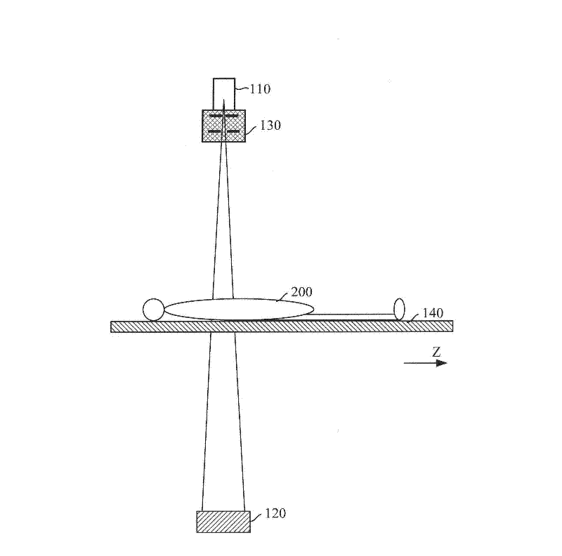
technical field [0001] The present invention relates to the technical field of computerized tomography (Computed Tomography, CT), in particular to a CT device and a topograph (TOPO image) imaging method. Background technique [0002] Before the CT equipment performs tomography, it usually acquires an anteroposterior or lateral scout image, and then selects an area to be scanned on the scout image, so as to perform tomography on the area. [0003] Scout images are similar to traditional X-ray exposure imaging. Such as figure 1 As shown, in the process of scout imaging, the X-ray tube 110 and the detector 120 for receiving X-rays are usually fixed, and a hospital bed 140 for carrying the scanning object 200 is moved, and the X-rays emitted by the X-ray tube 110 are always on the The scanning object 200 is exposed, and the detector 120 receives X-rays to form original data. After the original data is reconstructed, a positioning image can be obtained. figure 1 Also shown is ...

Claims


Application Information

Patent Timeline
Patent Type & Authority Applications(China)
IPC IPC(8): A61B6/03
Inventor 杜剑邵军明
Owner SIEMENS SHANGHAI MEDICAL EQUIP LTD
Learn More